Supercharge Your Innovation With Domain-Expert AI Agents!

Methods of Encapsulating Surface Mount Components

A packaging surface, surface mount technology, applied in the direction of electrical components, impedance networks, etc., to prevent cracking

Inactive Publication Date: 2011-12-14
WUHAN WINNINGCHINA MICROSYST TECH
View PDF0 Cites 0 Cited by
  • Summary
  • Abstract
  • Description
  • Claims
  • Application Information

AI Technical Summary

Problems solved by technology

[0004] The technical problem to be solved by the present invention is to solve the problem of low yield when using the molded encapsulation process to encapsulate surface mount components

Method used


Image

  • Methods of Encapsulating Surface Mount Components
  • Methods of Encapsulating Surface Mount Components
  • Methods of Encapsulating Surface Mount Components

Examples


Embodiment Construction

[0025] The present invention will be described in detail below in conjunction with the accompanying drawings.

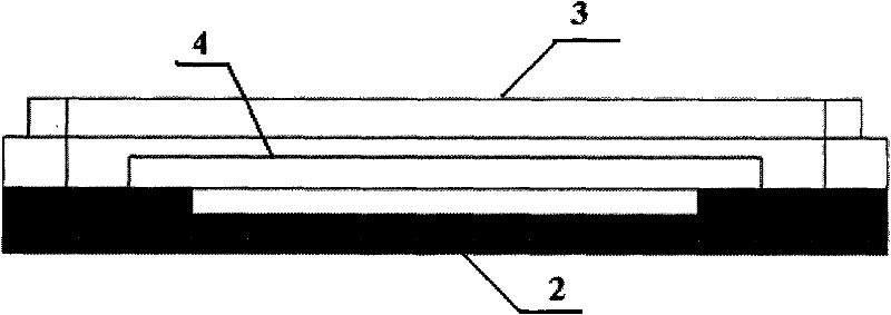
[0026] see Figure 7 , Figure 8 with Figure 9 , the present invention comprises the following steps:

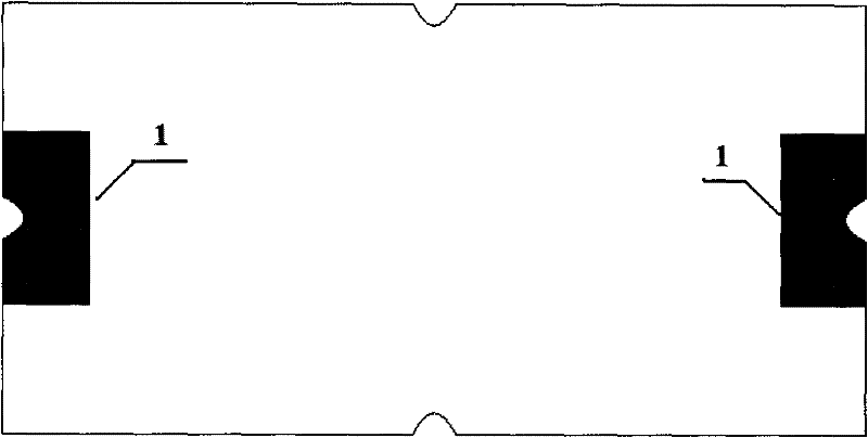
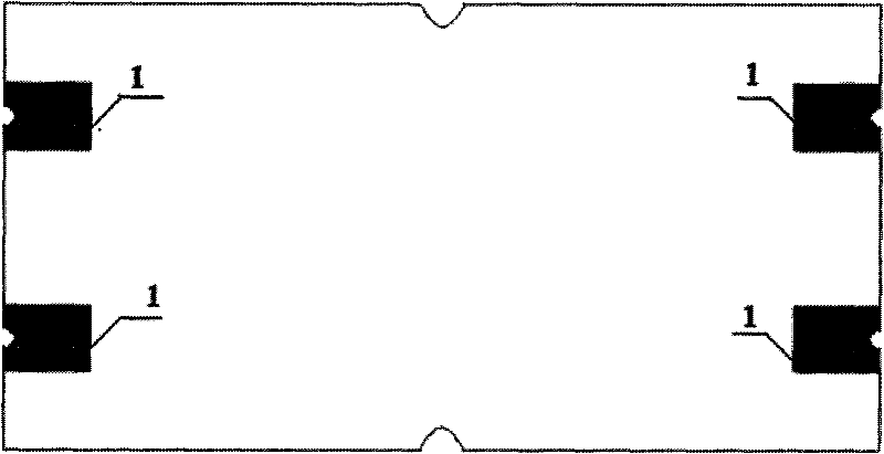
[0027] A10. First print a layer of solder 5 on the solder joint (i.e. electrode 1) on the base 2 of the surface mount component or on the position corresponding to the solder joint on the substrate 7, and then print a layer of solder 5 on other parts Filled solder or filled epoxy resin 6 with the same thickness, the filled solder or filled epoxy resin 6 and the above-mentioned solder 5 are provided with a gap 15, and the two cannot contact each other to ensure that the solder 5 is filled with solder or filled with epoxy resin 6. It is non-conductive between them to prevent the short circuit of the solder joints of the base 2 of the surface mount components. The above printings are all screen printing; filled with solder or filled with epoxy resin 6 and printed ...


PUM


Abstract

The invention discloses a method for encapsulating surface mount components. Filling solder or filling epoxy resin is pre-printed on the base or substrate of the surface mount components, filling most of the gaps between the two, and injection molding During the process, only a small amount of molding compound flows into the gap between the two. Therefore, the base is no longer damaged by the injection pressure, which effectively prevents the cracking of the base and improves the yield of the product. Mass production of components provides a guarantee.

Description

technical field [0001] The invention relates to an integrated circuit packaging process, in particular to a method for packaging surface mount components, and is particularly suitable for molding and packaging SMT crystal resonators or oscillators. Background technique [0002] Surface Mount Technology (SMT for short) is a new generation of electronic assembly technology, which compresses traditional electronic components into devices with only a few tenths of the volume, thus realizing high-density, high-reliability, Miniaturization, low cost and automation of production, currently, the components used are called surface mount components SMD. As a new generation of electronic assembly technology, SMT is widely used in electronic product assembly in various fields. Its application range involves aerospace, aviation, communication, computer, medical electronics, automobile, office automation, household appliances and other industries. [0003] In most SMT electronic produc...

Claims


Application Information

Patent Timeline
Patent Type & Authority Patents(China)
IPC IPC(8): H03H3/02
Inventor 刘胜刘勇曾珂范旺生
Owner WUHAN WINNINGCHINA MICROSYST TECH
Features
  • R&D
  • Intellectual Property
  • Life Sciences
  • Materials
  • Tech Scout
  • Unparalleled Data Quality
  • Higher Quality Content
  • 60% Fewer Hallucinations
Learn More