Abseiling device

A rope, original position technology, used in life-saving equipment, building rescue, etc., can solve problems such as dropping loads too quickly

Active Publication Date: 2010-06-02
SKYLOTEC GMBH
View PDF1 Cites 4 Cited by
  • Summary
  • Abstract
  • Description
  • Claims
  • Application Information

AI Technical Summary

Problems solved by technology

But it takes some experience to correctly adjust the jacking force to each load weight
Do not rule out incorrect operations, which could lead to lowering the load too quickly or also to the locking rope device

Method used


Image

  • Abseiling device
  • Abseiling device
  • Abseiling device

Examples


Embodiment Construction

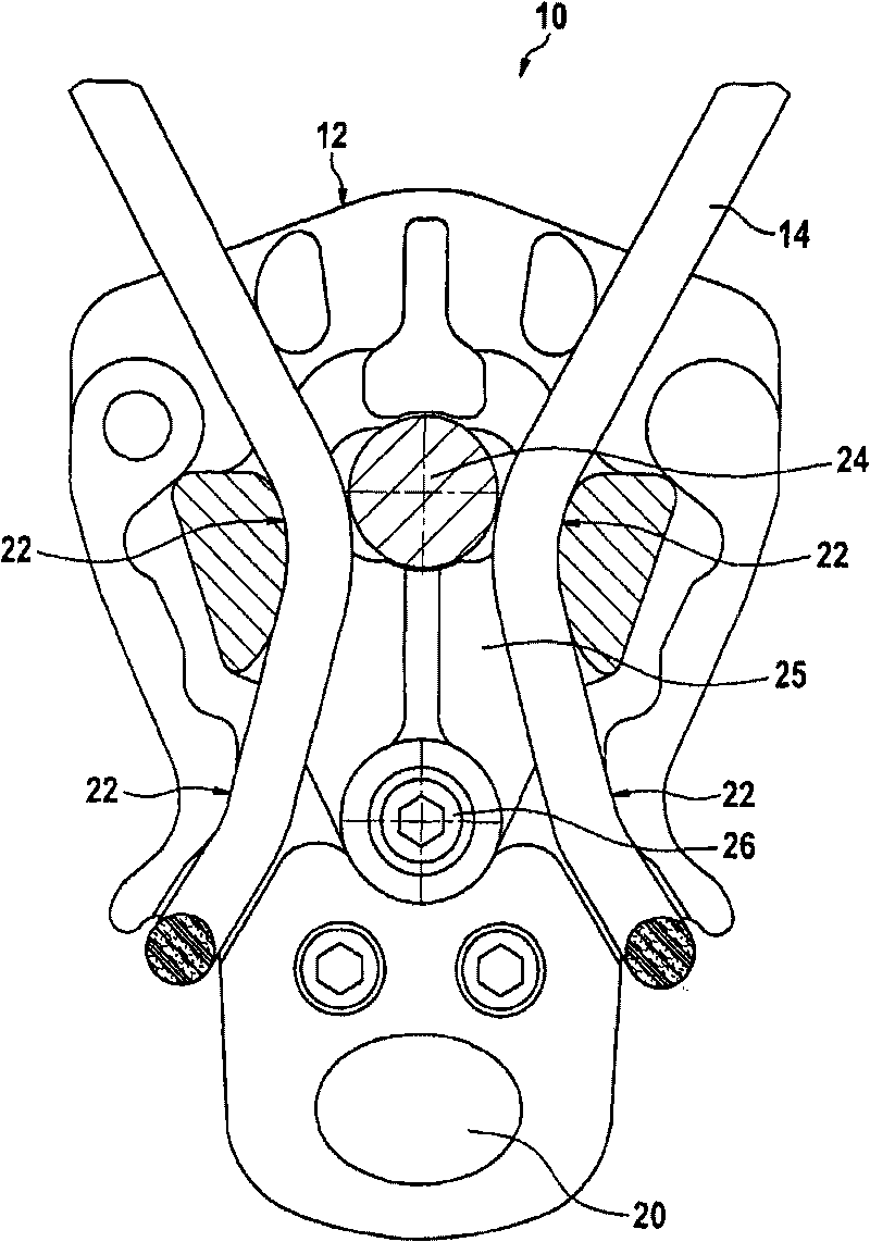
[0027] figure 1 The rope device 10 is shown with a housing 12 in which the rope 14 is guided through the rope device 10.

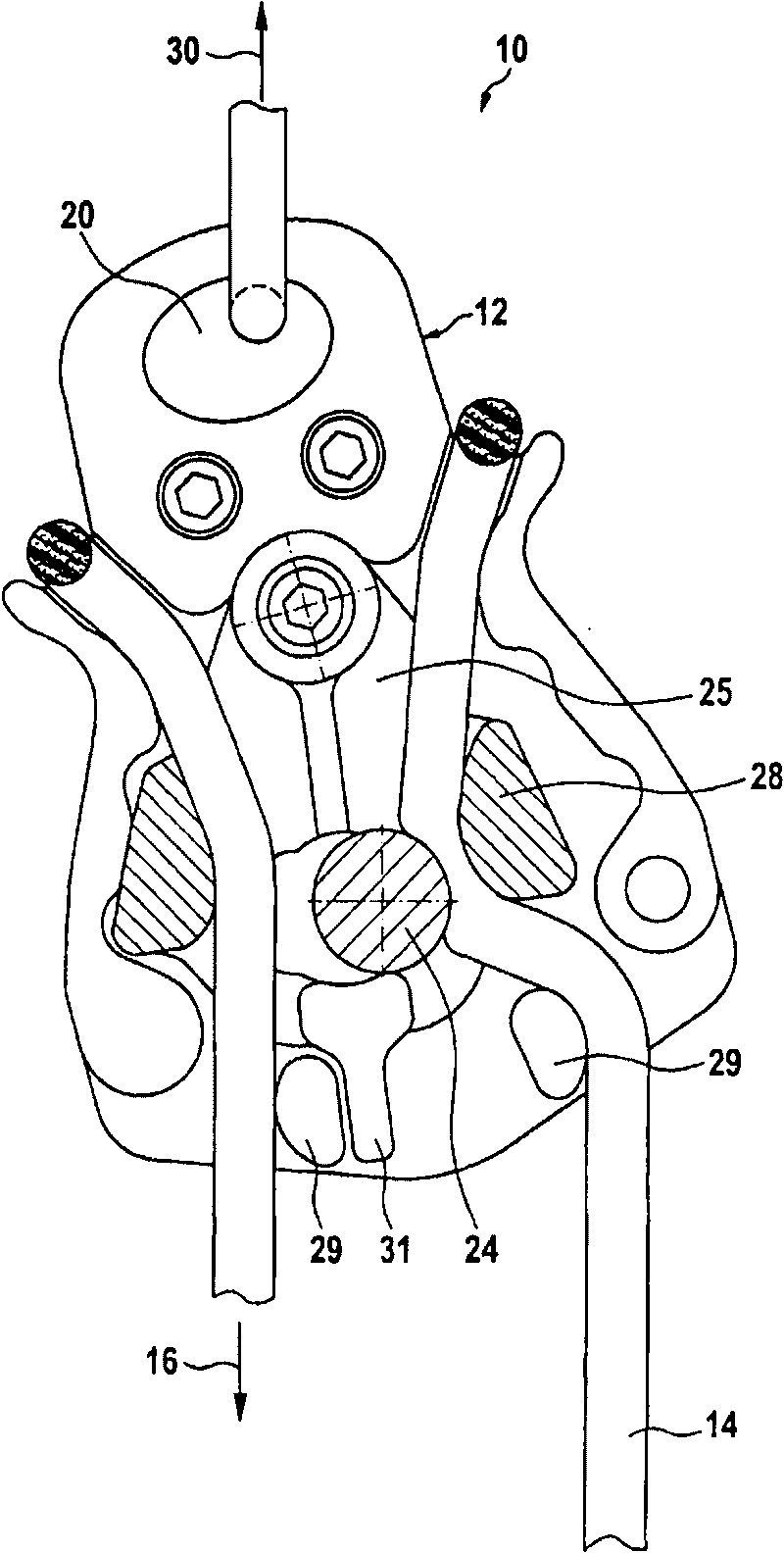
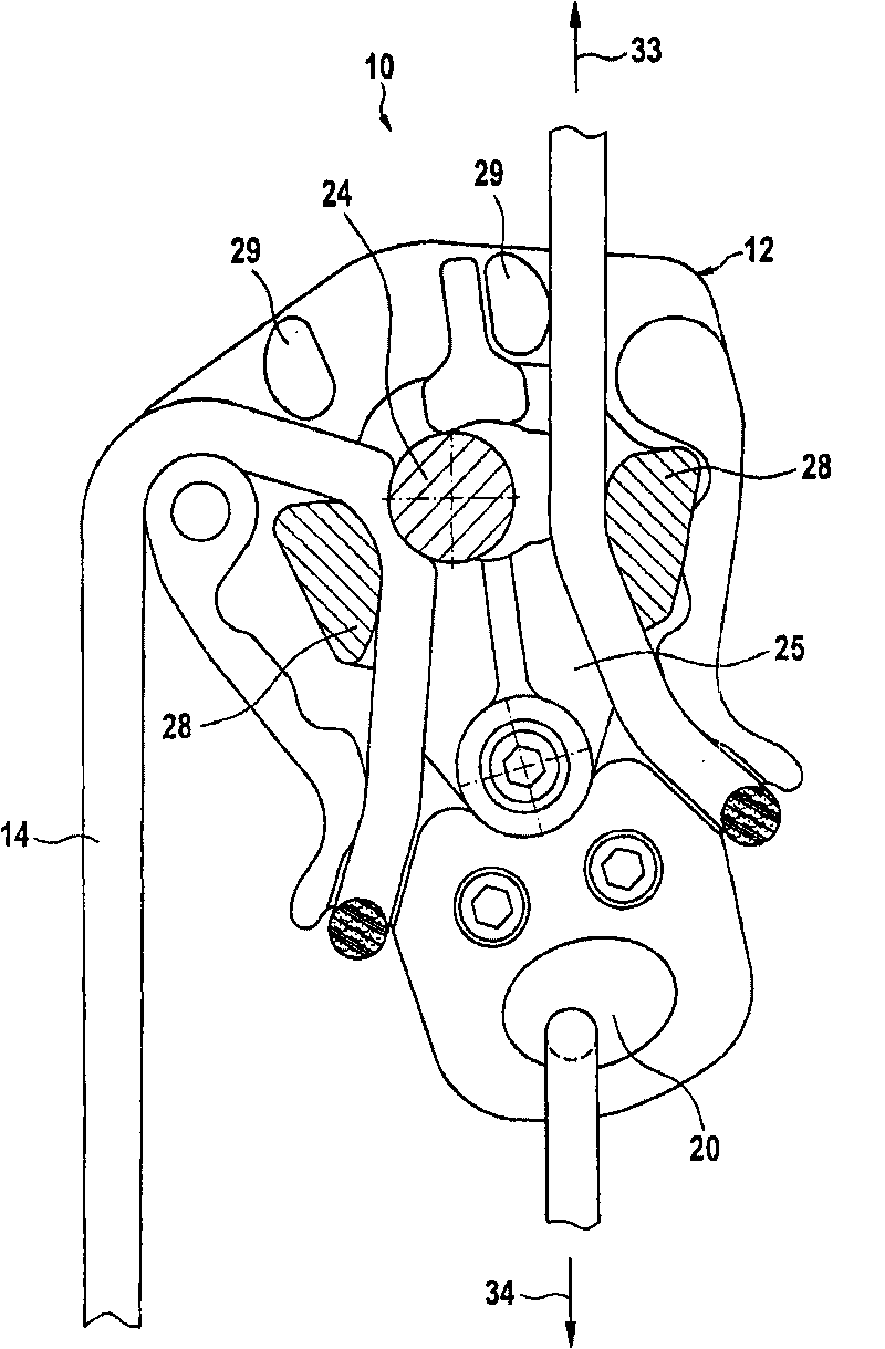
[0028] The rope device 10 has a cutout 20 on which a load to be lowered or a seat belt of a person can be fixed, and the rope device 10 is used to descend from a higher point to a lower point. But the fracture 20 can also be used for swing operation (see figure 2 ) To fix the rope device 10 when used. The rope device 10 has a friction-guided travel path 22 which is directly close to the brakeable shaft 24, which is braked by a centrifugal brake.

[0029] A friction-guided travel path 22 is guided by a movable, here deflectable part 25 which is rotatably supported on the housing 12 on a shaft 26. in figure 1 The position shown deflectable member 25 is in its unloaded original position, here an intermediate position, from which the member can be deflected in two directions. The deflectable component 25 has two jaws 28, which form a friction-guided stroke path ...


PUM


Abstract

An abseiling device for braking a load (16) which is guided on a rope (14) and can be fastened to the abseiling device (10), in which the rope (14) runs through the abseiling device (10) with frictional guidance over a distance (22), wherein at least one portion of the distance (22) is guided via a part (25) of the abseiling device (10), which part can be moved out of a load-free initial position relative to a housing (12) of the abseiling device and, when a load is suspended, generates a frictional force, which is dependent on the weight of the load (16), on the rope (14).

Description

Technical field [0001] The present invention relates to a rope device for braking a load guided on a rope. The load can be fixed on the rope device, wherein the rope passes through the rope device frictionally guided on a travel path. Background technique [0002] Such a device is known from DE 10 2006 009 332 A1. In the known device, in addition to the friction-guided stroke path, a brakeable shaft is provided for the rope, on which the rope is pressed with a given pressing force. Therefore, the advantage of this kind of rope device is that the brake of the shaft can be configured to be smaller, because the brake of the shaft supports its braking work through a friction-guided stroke path. The jacking pressure can be adjusted to adapt the rope device to loads of different weights, and the rope can be pushed against the brakeable shaft by the jacking pressure. But it takes some experience to adjust the top pressure to each load weight correctly. Misoperations are not ruled out...

Claims


Application Information

Patent Timeline
Patent Type & Authority Applications(China)
IPC IPC(8): A62B1/10A62B1/14
CPCA62B1/10A62B1/14
Inventor U·科沃特希
Owner SKYLOTEC GMBH
Why Eureka
Try Eureka