Articulated structure for a multi-axis robot, and a robot including such a structure

A multi-axis robot and articulated technology, applied in manipulators, mechanical equipment, program-controlled manipulators, etc., can solve the problems of limiting the speed of tool movement, increasing the inertia of the forearm, etc., and achieve the effect of reducing inertia

Active Publication Date: 2010-06-09
STAUBLI FAVERGES SA
View PDF6 Cites 14 Cited by
  • Summary
  • Abstract
  • Description
  • Claims
  • Application Information

AI Technical Summary

Problems solved by technology

This movement increases the inertia of the forearm, which limits the speed at which the tool can be moved

Method used


Image

  • Articulated structure for a multi-axis robot, and a robot including such a structure
  • Articulated structure for a multi-axis robot, and a robot including such a structure
  • Articulated structure for a multi-axis robot, and a robot including such a structure

Examples


Embodiment Construction

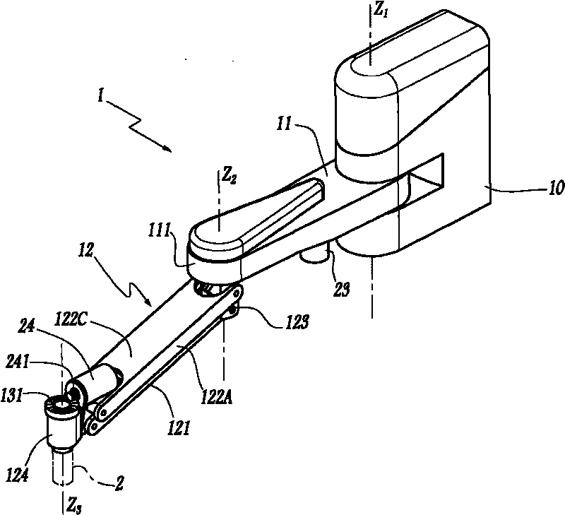
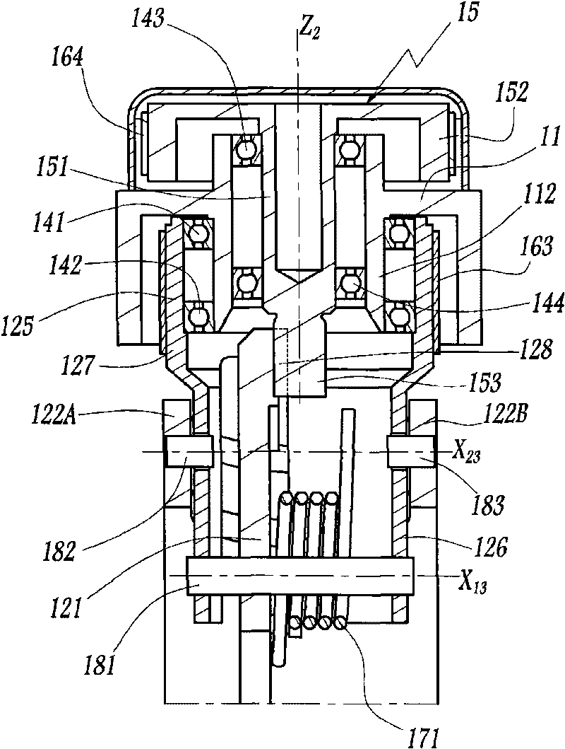
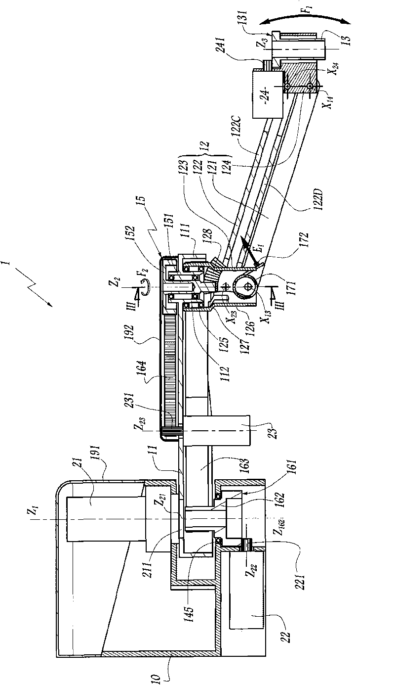
[0034] exist Figure 1 to Figure 3 The structure 1 visible in FIG. 1 forms part of a multi-axis robot which also includes an electronic control unit, a bundle of cables, and / or a bundle of pipes feeding pressurized gas, and other accessories, which are not shown for clarity of the figure. Likewise, these components are not shown in the robots of other embodiments.

[0035] Structure 1 is used to move tool 2 to various positions, the tool is only in figure 1 Schematically indicated in dash-dotted lines in , the tool moves along a path extending not only in the horizontal plane but also perpendicularly with respect to this plane. For example, tool 2 may be a gripper tool.

[0036] The structure 1 comprises a base 10 which is fixed relative to where the structure 1 is mounted. The base is formed for around the vertical axis Z 1 U-shaped piece (clevis) of the articulated arm 11 .

[0037] On the base 10, a first actuator 21 composed of a rotating gear reduction motor (electri...


PUM


Abstract

The articulated structure (1) with three degrees of freedom for a multi-axis robot comprises a stationary base (10); an arm (11) hinged to the base about a first axis (Z1); a forearm (12) hinged to the arm about a second axis (Z2) parallel to the first axis, the forearm forming a deformable parallelogram structure and comprising a first connecting rod (121) and a second connecting rod (122) that are hinged to two plates (123, 124) about respective axes (X13, X14, X23, X24) that are perpendicular to the first and second axes. This structure also comprises a first electric actuator (21) controlling pivoting of the arm (11) about the first axis (Z1); a second electric actuator (22) controlling pivoting of the forearm (12) about the second axis (Z2); and a third electric actuator (23) controlling pivoting of one of the first connecting rod (121) relative to the plates (123, 124) about the axes (X14, X24) that are perpendicular to the first and second axes (Z1, Z2). The third actuator (23) is mounted on the base (10) or on the arm (11).

Description

technical field [0001] The invention relates to an articulated structure having at least three degrees of freedom for a multi-axis robot, and also to a multi-axis robot incorporating such a structure. Background technique [0002] In the field of multi-axis robotics, parts must sometimes be manipulated rapidly along near-planar paths. This applies when, for example, parts moving on a conveyor belt are picked up and placed on a plane conditioning piece. SCARA-type robots are suitable for working in a horizontal plane. Sometimes such robots are also adapted to be able to move in a vertical plane. In such robots, vertical motion is typically provided by a ball screw system near the tool, at the end of an articulated structure commonly called the manipulator. This creates a high inertia for the articulated structure, limiting the speed at which the tool can be moved. Also, under certain conditions of use, the size of the ball screw system may be a hindrance. [0003] JP-A-5...

Claims


Application Information

Patent Timeline
Patent Type & Authority Applications(China)
IPC IPC(8): B25J18/00B25J9/02
CPCB25J9/046B25J9/042B25J9/1065Y10T74/20317Y10T74/20305Y10T74/20329
Inventor 约瑟夫·帕洛樊尚·热拉特艾瑞克·撒莱特
Owner STAUBLI FAVERGES SA
Why Eureka
Try Eureka