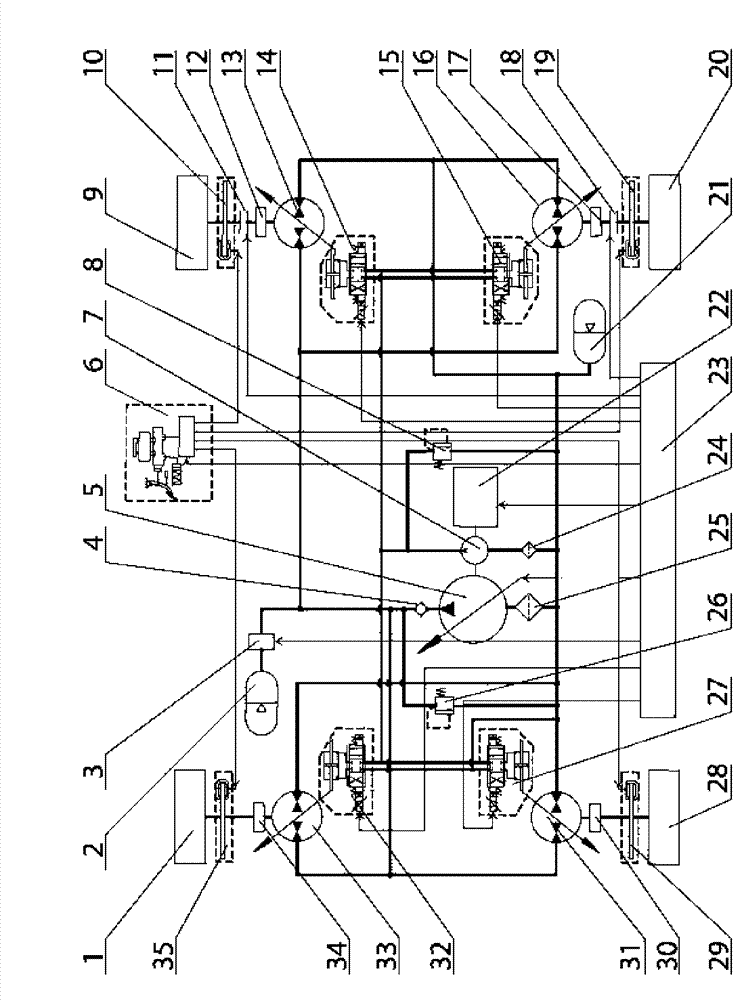
Driving system of wheel-drive type hydrostatic transmission hybrid vehicle
A hybrid vehicle and wheel-side drive technology, which is applied in the transmission system field of hybrid vehicles, can solve the problems of inflexible layout of the driving torque structure of the driving wheels and unreasonable distribution of the axle structure, etc., and achieve flexible vehicle body structure layout, The effect of shortening the design cycle and increasing stability
- Summary
- Abstract
- Description
- Claims
- Application Information
AI Technical Summary
Problems solved by technology
Method used
Image
Examples
specific Embodiment approach 1
[0016] Specific implementation mode one: combine figure 1 Describe this embodiment, present embodiment comprises right front wheel 1, left front wheel 28, right rear wheel 9, left rear wheel 20, right rear wheel reducer 12, left rear wheel reducer 17, left front wheel reducer 30, right front Wheel reducer 34, right rear wheel clutch 11, left rear wheel clutch 18, friction brake controller assembly 6, right rear wheel friction brake 10, left rear wheel friction brake 19, left front wheel friction brake 29 and right front wheel friction brake Brake 35; also includes power element, right rear wheel hydraulic pump / motor 13, left rear wheel hydraulic pump / motor 16, left front wheel hydraulic pump / motor 31, right front wheel hydraulic pump / motor 33, high pressure hydraulic accumulator 2 , low pressure hydraulic accumulator 21, left front wheel hydraulic pump / motor variable device 27, right rear wheel hydraulic pump / motor variable device 14, left rear wheel hydraulic pump / motor varia...
specific Embodiment approach 2
[0026]Specific implementation mode two: combination figure 1 Describe this embodiment, the difference between this embodiment and specific embodiment 1 is that a power oil circuit relief valve 26 is added, which is connected between the oil outlet of the constant pressure variable pump 5 and the inlet and outlet of the low pressure hydraulic accumulator 21 There is a power oil relief valve 26, the oil inlet of the power oil relief valve 26 is connected to the oil outlet of the constant pressure variable pump 5, and the oil discharge port of the power oil relief valve 26 is connected to the low-pressure hydraulic accumulator 21 The oil inlet and outlet connections. Other compositions and connection methods are the same as those in Embodiment 1.
specific Embodiment approach 3
[0027] Specific implementation mode three: combination figure 1 Describe this embodiment, the difference between this embodiment and the specific embodiment is that a control oil circuit relief valve 8 is added, and a control valve is connected between the oil outlet of the quantitative pump 7 and the inlet and outlet of the low-pressure hydraulic accumulator 21. The oil relief valve 8 controls the connection between the oil inlet of the oil relief valve 8 and the oil outlet of the quantitative pump 7, and controls the oil discharge port of the oil relief valve 8 and the oil inlet and outlet of the low-pressure hydraulic accumulator 21 connect. Other compositions and connection methods are the same as those in Embodiment 1.
PUM
 Abstract
Description
Claims
Application Information
 - R&D
- Intellectual Property
- Life Sciences
- Materials
- Tech Scout
- Unparalleled Data Quality
- Higher Quality Content
- 60% Fewer Hallucinations
Browse by: Latest US Patents, China's latest patents, Technical Efficacy Thesaurus, Application Domain, Technology Topic, Popular Technical Reports.
© 2025 PatSnap. All rights reserved.Legal|Privacy policy|Modern Slavery Act Transparency Statement|Sitemap|About US| Contact US: help@patsnap.com

