
Light source module

A technology of light source module and light, which is applied in the direction of light source, point light source, semiconductor device of light-emitting element, etc., and can solve problems such as difficult installation and maintenance

Inactive Publication Date: 2010-06-09
HONG FU JIN PRECISION IND (SHENZHEN) CO LTD +1
View PDF1 Cites 0 Cited by
  • Summary
  • Abstract
  • Description
  • Claims
  • Application Information

AI Technical Summary

Problems solved by technology

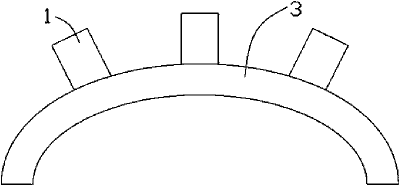
[0005] However, the above-mentioned LED light-emitting board needs to be equipped with a plurality of light-emitting diodes 1, and its installation and maintenance are very difficult.

Method used


Image

  • Light source module
  • Light source module
  • Light source module

Examples


Embodiment Construction

[0012] The present invention will be further described in detail below in conjunction with the accompanying drawings.

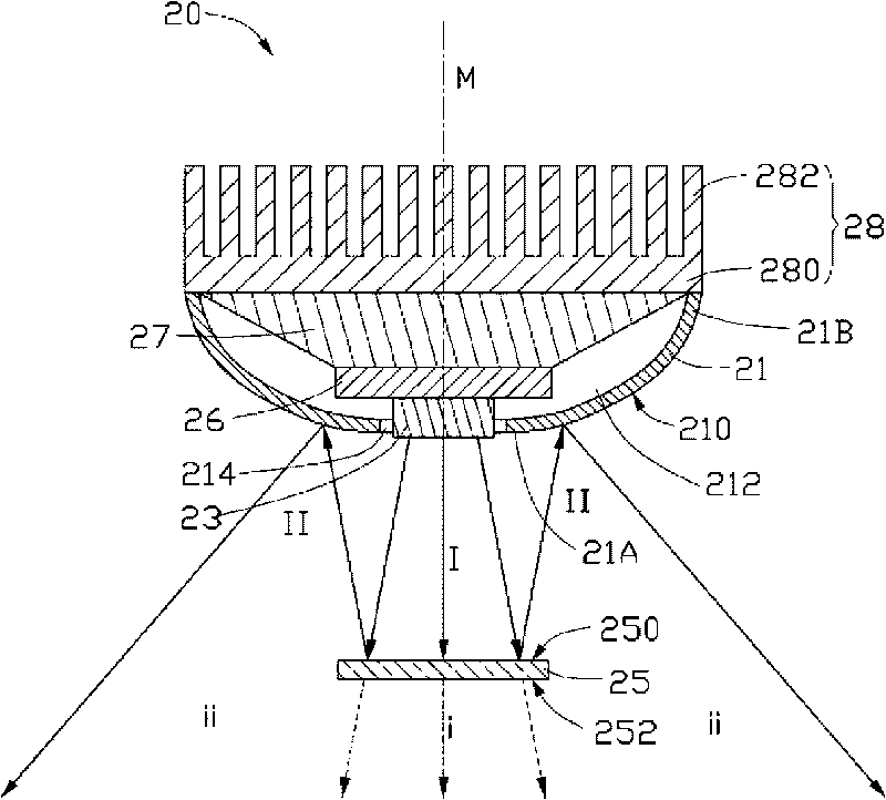
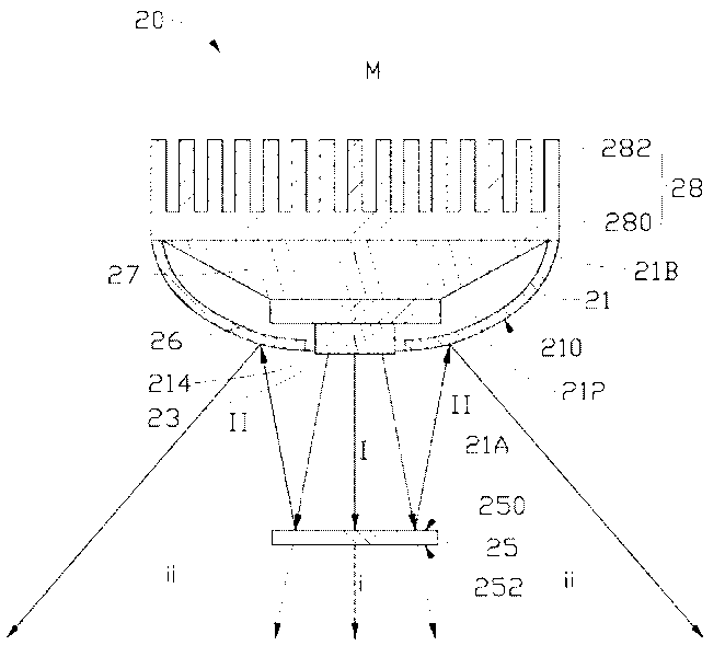
[0013] see figure 2 , a light source module 20 provided by an embodiment of the present invention includes a reflector 21 , a light emitting element 23 and a semi-reflective and semi-transmissive optical sheet 25 .

[0014] The reflector 21 is used for reflecting light, and has a geometric central axis M and a reflective surface 210 surrounding the geometric central axis M. Specifically, the reflector 21 has an arc-shaped profile, and the arc-shaped profile forms a receiving space 212 around the geometric central axis M. The reflective surface 210 is a convex surface of the arc-shaped profile, that is, the reflective surface 210 is an arc surface. The arc profile has a first end 21A and a second end 21B along the direction of the geometric central axis M. The reflective surface 210 intersects with a section perpendicular to the geometric center axis M to f...


PUM


Abstract

The invention relates to a light source module with uniform light field. The light source module comprises a reflex housing, a luminous element and a semi-reflection semi-transmission optical sheet. The reflex housing comprises a geometrical central axis and a reflecting surface around the geometrical central axis. The luminous element is arranged on the geometrical central axis. The optical sheet comprises an incident surface which is opposite to the luminous element and the reflex housing. The optical sheet is used for transmitting partial light rays sent by the luminous element and incident on the incident surface to a first optical region at one side of the optical sheet far away from the luminous element and reflecting the rest light rays incident on the incident surface to the reflecting surface so that the rest light rays are reflected to a second optical region around the first optical region through the reflecting surface. The light rays of the first optical region and the second optical region are coupled optically so as to form the uniform light field integrally.

Description

technical field [0001] The invention relates to a light source module, in particular to a light source module with a uniform light field. Background technique [0002] Currently, Light Emitting Diodes (LEDs) are gradually replacing Cold Cathode Fluorescent Lamps (CCFLs) as light emitting diodes in lighting devices due to their good light quality (that is, the spectrum emitted by the LED light source) and high luminous efficiency. For the component, please refer to the article "Solid-State Lighting: Toward Superior Illumination" published by Michael S. Shur et al. in the document Proceedings of the IEEE, Vol.93, No.20 (December 2005). [0003] Existing light-emitting diodes usually have approximately circularly symmetrical light fields, and the light intensity distribution of these light fields is uneven, that is, the light intensity in the center is strong, and the light intensity in the area diffused from the center becomes weaker and weaker. However, due to the advantages...

Claims


Application Information

Patent Timeline
Patent Type & Authority Applications(China)
IPC IPC(8): F21V7/04F21V5/08F21V13/04F21Y101/02
CPCF21V29/02F21V7/0016F21V29/2206F21Y2101/02F21V29/74F21V29/763F21Y2115/10
Inventor 林大为
Owner HONG FU JIN PRECISION IND (SHENZHEN) CO LTD
Learn More