Electromagnetic flow meter excitation control system based on high and low voltage power switching

An electromagnetic flowmeter and power switching technology, which is applied in the application of electromagnetic flowmeter to detect fluid flow, volume/mass flow generated by electromagnetic effects, measurement flow/mass flow, etc., can solve the limitation of input and output pressure difference and large heat dissipation , large circuit board area, etc.

Active Publication Date: 2010-06-09
HEFEI UNIV OF TECH +1
View PDF1 Cites 38 Cited by
  • Summary
  • Abstract
  • Description
  • Claims
  • Application Information

AI Technical Summary

Problems solved by technology

But this electromagnetic flowmeter excitation control system still has the following deficiencies: (1) Due to the high-voltage power supply, after the square-wave excitation enters the half-cycle steady state, the voltage drop on the linear power supply is very large, which makes it heat The dissipation is very large, and the power utilization efficiency is low; (2) Although the power supply bypass circuit can effectively solve the heat dissipation problem, the circuit occupies a large area, and the power utilization efficiency has not been improved; (3) when the linear power supply is working, its The input and output pressure difference is limited, which also limits the further increase of the excitation frequency

Method used


Image

  • Electromagnetic flow meter excitation control system based on high and low voltage power switching
  • Electromagnetic flow meter excitation control system based on high and low voltage power switching
  • Electromagnetic flow meter excitation control system based on high and low voltage power switching

Examples


Embodiment Construction

[0016] The present invention will be further described below in conjunction with accompanying drawing:

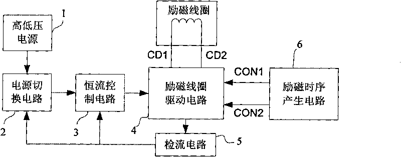
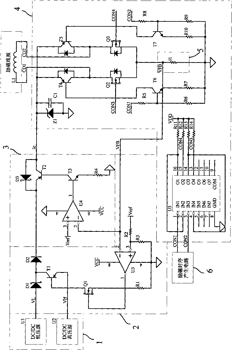
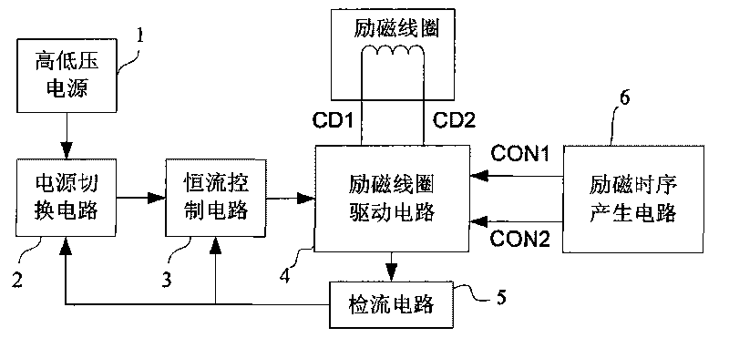
[0017] The present invention is based on the applied invention patent "A Single / Dual Frequency Electromagnetic Flowmeter Excitation Control System Based on Linear Power Supply", and improves the excitation power supply part and the constant current control part. Its purpose is to improve the efficiency of power utilization and to further broaden the range of excitation frequency on the premise of ensuring the stability of the zero point of the electromagnetic flowmeter, so as to provide conditions for the increase of excitation frequency in slurry measurement. The design idea of ​​the present invention is to convert the excitation working voltage source into a current source through current negative feedback constant current control, so as to provide a constant excitation steady-state current for the excitation coil. Provided by the low-end current detection circuit of the ...


PUM


Abstract

The invention relates to an electromagnetic flow meter excitation control system based on high and low voltage power switching, comprising a high voltage power and a low voltage power, a power switching circuit, a constant-current control circuit, a filed coil driving circuit, a current detecting circuit and an excitation timing sequence generation circuit. An excitation working power is provided by switching the high voltage power and the low voltage power via the power switching circuit according to excitation current response situation in a time sharing manner so as to quicken the response speed of square wave excitation current and improve power utilization ratio; the constant-current control circuit supplies power to the filed coil driving circuit so as to cause the steady-state value of the excitation current to be constant; the filed coil driving circuit is composed of an H bridge and a control circuit thereof to realize square wave excitation; the current detecting circuit is bridged between the lower end of the H bridge and reference ground; and the excitation timing sequence generation circuit is mainly composed of an processing core MCU for processing the signals of the electromagnetic flow meter, and the like. The excitation control system can obviously enhance the range of excitation frequency, lower circuit energy consumption and improve power utilization efficiency in the condition of ensuring the stable zero point of the electromagnetic flow meter, so as to be applicable to accuracy measurement of size fluid.

Description

technical field [0001] The invention relates to the field of flow detection, and is an electromagnetic flowmeter excitation that uses a high-voltage power supply and a low-voltage power supply to supply power at the same time, switches the excitation working power supply by a power switching circuit, and controls the current of the excitation coil by a constant current control circuit to realize high-efficiency and high-frequency excitation. Control System. Background technique [0002] The electromagnetic flowmeter applies a magnetic field to the measured fluid through the excitation coil, and the measured fluid moves in the magnetic field to induce an induced electromotive force, and the fluid flow velocity can be obtained by detecting and processing the electromotive force signal, thereby realizing flow measurement. At present, the excitation method is mainly low-frequency square wave excitation, that is, the excitation coil is powered by a constant current source, and th...

Claims


Application Information

Patent Timeline
Patent Type & Authority Applications(China)
IPC IPC(8): G01F1/58G01F1/60
Inventor 徐科军杨双龙王刚石磊李积春
Owner HEFEI UNIV OF TECH
Why Eureka
Try Eureka