
Liquid crystal display

A liquid crystal display, liquid crystal display panel technology, applied in the direction of instruments, nonlinear optics, optics, etc., can solve the problems of increasing the size of the liquid crystal display 100, the design concept of the liquid crystal display does not match, etc., to reduce the tearing of the tape or the peeling of the chip probability, and the effect of improving the pass rate of the test

Inactive Publication Date: 2012-12-26
INNOLUX CORP
View PDF0 Cites 0 Cited by
  • Summary
  • Abstract
  • Description
  • Claims
  • Application Information

AI Technical Summary

Problems solved by technology

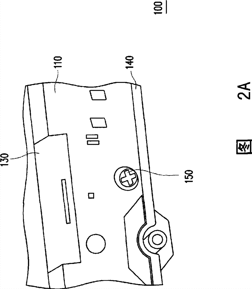
Although this method allows the control circuit board 110 to be fixed on the frame 140 and allows the control circuit board 110 to move along with the liquid crystal display panel 120, the control circuit board 110 must be placed in the same position as the liquid crystal display panel 120 using this method. Therefore, the overall size of the liquid crystal display 100 will be increased to accommodate the control circuit board 110 located on the same plane as the liquid crystal display panel 120
In addition, the metal dome 170 must form a certain height in order to be pressed by the front frame or the back frame, so the thickness of the front frame needs to be increased to accommodate the metal dome 170, which is inconsistent with the design concept of thinning the liquid crystal display 110

Method used


Image

  • Liquid crystal display
  • Liquid crystal display
  • Liquid crystal display

Examples


no. 1 example

[0078] Figure 5A is a schematic diagram of the liquid crystal display of the first embodiment of the present invention, and Figure 5B for Figure 5A partial sectional view. Please also refer to Figure 5A and Figure 5B The liquid crystal display 1000 includes a liquid crystal display panel 1100 , a control circuit board 1200 , a plurality of flexible joints 1300 , a frame 1400 and a plurality of limiting structures 1500 . The control circuit board 1200 is disposed on one side of the liquid crystal display panel 1100 and has a plurality of openings 1202 . The flexible joint 1300 is connected between the liquid crystal display panel 1100 and the control circuit board 1200 . The frame 1400 is arranged between the liquid crystal display panel 1100 and the control circuit board 1200, and the limiting structure 1500 is arranged on the frame 1400, wherein the limiting structure 1500 corresponds to the opening 1202, and the limiting structure 1500 and the corresponding edge of...

no. 2 example

[0088] This embodiment is substantially the same as the first embodiment, and the same or similar element numbers represent the same or similar elements.

[0089] Figure 7A It is a perspective view of the liquid crystal display of the second embodiment of the present invention, Figure 7B for Figure 7A The partial three-dimensional section view of Figure 7C for Figure 7B schematic diagram. Please also refer to Figure 7A , Figure 7B and Figure 7CThe liquid crystal display 2000 includes a liquid crystal display panel 1100 , a control circuit board 1200 , a flexible joint 1300 , a plurality of fixing members 2400 , a frame 2500 and a plurality of buffer blocks 2600 . The control circuit board 1200 is disposed on one side of the liquid crystal display panel 1100 and has a plurality of first openings 1210 . The flexible joint 1300 is connected between the liquid crystal display panel 1100 and the control circuit board 1200 . Wherein, the liquid crystal display panel...


PUM


Abstract

The invention discloses a liquid crystal display, which comprises a liquid crystal display panel, a control circuit board, a plurality of flexible connecting parts, a frame and a plurality of limiting structures, wherein the control circuit is configured on one side of the liquid crystal display panel and has a plurality of openings; the flexible connecting parts are connected between the liquid crystal display panel and the control circuit board; the frame is configured between the liquid crystal display panel and the control circuit board; the limiting structures are configured on the frame and correspondingly inserted into the openings; and gaps are preserved between the limiting structures and the edges of the corresponding openings to control the circuit board to move a little with the liquid crystal display panel.

Description

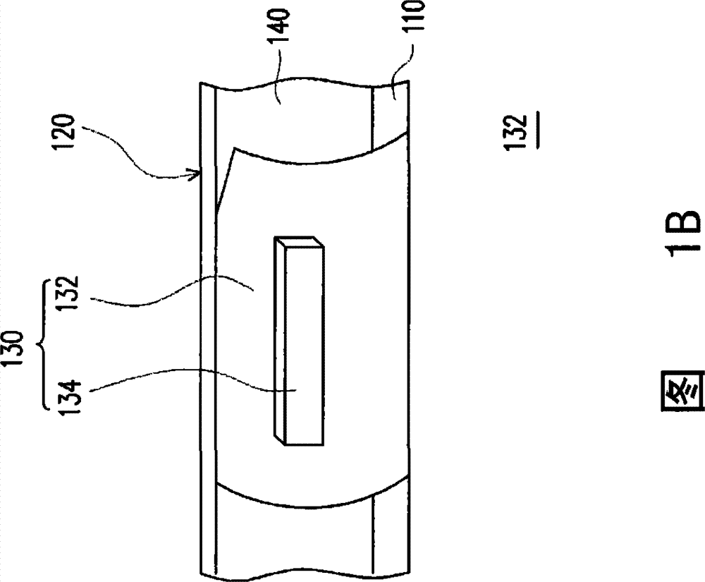
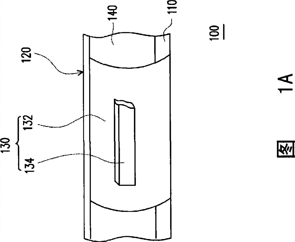
technical field [0001] The present invention relates to a liquid crystal display, and in particular to a liquid crystal display with a good test pass rate. Background technique [0002] With the vigorous development of science and technology and people's pursuit of life comfort, the module size of the liquid crystal display is also rapidly enlarged, and the manufacturing and assembly tolerances of the mechanical components of the liquid crystal display are also increased. [0003] Figure 1A is a schematic diagram of a known liquid crystal display. Please refer to Figure 1A , in the known liquid crystal display 100 , the control circuit board 110 and the liquid crystal display panel 120 are connected by a flexible joint 130 . Generally speaking, the control circuit board 110 can be completely fixed on the frame 140 of the liquid crystal display 100 by various methods, such as locking with screws or using metal shrapnel, and the control circuit board 110 cannot be opposed t...

Claims


Application Information

Patent Timeline
Patent Type & Authority Patents(China)
IPC IPC(8): G02F1/13
Inventor 李汉杰
Owner INNOLUX CORP
Learn More