Self-excitation multi-wavelength dynamically dispatched optical network unit in passive optical network

A dynamic scheduling and self-excitation technology, applied in the field of optical communication, can solve problems such as high cost and complex structure, and achieve the effect of improving utilization rate and increasing uplink transmission bandwidth

Inactive Publication Date: 2012-09-05
SHANGHAI JIAOTONG UNIV +1
View PDF0 Cites 0 Cited by
  • Summary
  • Abstract
  • Description
  • Claims
  • Application Information

AI Technical Summary

Problems solved by technology

However, this solution needs to send the seed excitation wavelength from the local OLT, and then send it to each ONU after power division at the remote node. Compared with the ONU self-excitation transmission technology, the structure is complex and the cost is high.

Method used


Image

  • Self-excitation multi-wavelength dynamically dispatched optical network unit in passive optical network
  • Self-excitation multi-wavelength dynamically dispatched optical network unit in passive optical network
  • Self-excitation multi-wavelength dynamically dispatched optical network unit in passive optical network

Examples


Embodiment 1

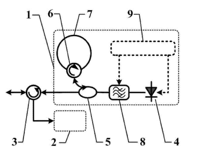
[0021] Such as figure 1 As shown, this embodiment includes: an uplink data transmitter 1, a downlink data receiver 2, and a first optical circulator 3, wherein: the output end of the first optical circulator 3 is connected to the downlink data receiver 2 to transmit downlink data optical signals , the input end of the first optical circulator 3 is connected to the uplink data transmitter 1 to transmit the uplink data optical signal, the downlink data receiver 2 is used to recover the downlink data, the uplink data transmitter 1 is used to generate the uplink data optical signal, the first optical ring The input / output end of the shaper 3 transmits the uplink data optical signal and the downlink data optical signal.

[0022] The uplink data transmitter 1 includes: FP multi-longitudinal mode laser 4, adjustable bandpass filter 8, 1×2 optical splitter / coupler 5, second optical circulator 6 and control module 9, the second optical ring The input end and the output end of the liner ...

Embodiment 2

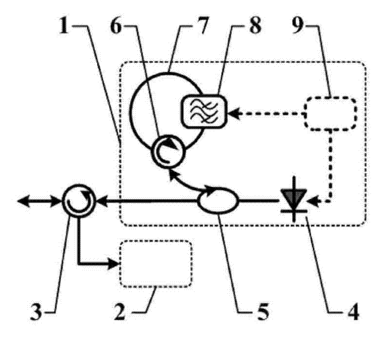
[0028] Such as figure 2 As shown, this embodiment includes: an uplink data transmitter 1, a downlink data receiver 2, and a first optical circulator 3, wherein: the output end of the first optical circulator 3 is connected to the downlink data receiver 2 to transmit downlink data optical signals , the input end of the first optical circulator 3 is connected to the uplink data transmitter 1 to transmit the uplink data optical signal, the downlink data receiver 2 is used to recover the downlink data, the uplink data transmitter 1 is used to generate the uplink data optical signal, the first optical ring The input / output end of the shaper 3 transmits the uplink data optical signal and the downlink data optical signal.

[0029] The uplink data transmitter 1 includes: FP multi-longitudinal mode laser 4, 1×2 optical splitter / coupler 5, second optical circulator 6, adjustable bandpass filter 8 and control module 9, the second optical ring The output end of the circulator 6 is conne...

Embodiment 3

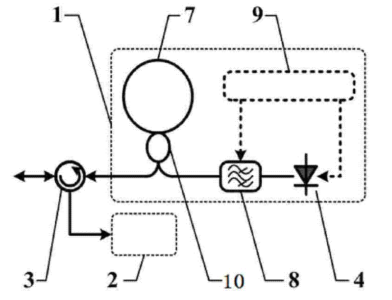
[0035] Such as image 3 As shown, this embodiment includes: an uplink data transmitter 1, a downlink data receiver 2, and a first optical circulator 3, wherein: the output end of the first optical circulator 3 is connected to the downlink data receiver 2 to transmit downlink data optical signals , the input end of the first optical circulator 3 is connected to the uplink data transmitter 1 to transmit the uplink data optical signal, the downlink data receiver 2 is used to recover the downlink data, the uplink data transmitter 1 is used to generate the uplink data optical signal, the first optical ring The input / output end of the shaper 3 transmits the uplink data optical signal and the downlink data optical signal.

[0036] The uplink data transmitter 1 includes: FP multi-longitudinal mode laser 4, adjustable bandpass filter 8, 2×2 optical splitter / coupler 10 and control module 9, 2×2 optical splitter / coupler 10 The two ports on the same side are directly connected to form a ...


PUM


Abstract

The invention discloses a self-excitation multi-wavelength dynamically dispatched optical network unit in passive optical network, belonging to the technical field of optical communication. The optical network unit comprises an uplink data transmitter, a downlink data receiver and a first optical circulator, wherein the output end of the first optical circulator is connected with the downlink data receiver for transmitting downlink data optical signals; the input end of the first optical circulator is connected with the uplink data transmitter for transmitting uplink data optical signals; andthe uplink data transmitter comprises a FP multi-longitudinal mode laser, an adjustable band-pass filter, an optical splitter / coupler and an optical reflection ring. In the invention, multi-wavelength dynamically modulated uplink optical carrier is generated based on the self-excitation working mode of the FP multi-longitudinal mode laser, thereby greatly increasing the uplink transmission bandwidth, flexibly and effectively sharing all uplink wavelength resources, improving the use ratio of the uplink wavelength resource, ensuring simple structure and low cost, according with the requirementof colourless transmission of the optical network unit and meeting the development requirement of dramatically increased uplink access ability for users.

Description

technical field [0001] The invention relates to a device in the technical field of optical communication, in particular to an optical network unit for self-exciting multi-wavelength dynamic scheduling in a passive optical network. Background technique [0002] In recent years, the development of passive optical network (PON) technology has gradually matured, and it has been widely deployed in the United States, South Korea, Japan and other countries. Many research institutions and communication companies at home and abroad have invested in research and development of the best broadband access solution. With the wide application of bandwidth-intensive services, such as video conferencing, high-definition television (HDTV), video on demand (VoD), or distributed computing applications in the optical access network, the optical network unit (ONU) at the user end Unit, ONU) requires an average uplink access bandwidth of at least gigabits per second, but currently the average upl...

Claims


Application Information

Patent Timeline
Patent Type & Authority Patents(China)
IPC IPC(8): H04B10/12H04B10/20H04B10/02H04Q11/00H04B10/25
Inventor 朱敏肖石林郭薇陈荷史杰
Owner SHANGHAI JIAOTONG UNIV
Why Eureka
Try Eureka