
Air inflow ducting device for vehicle engine

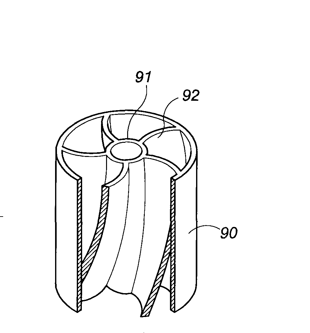
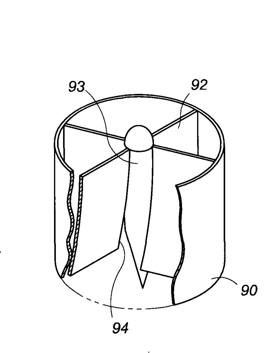
A technology for air guiding devices and vehicles, which is applied in the direction of power devices, vehicle components, and gas intake of power devices, and can solve uneven air intake, uneven air intake of spoilers, and uneven curvature of outward extension And other issues

Active Publication Date: 2013-02-20
杨仲玉
View PDF3 Cites 0 Cited by
  • Summary
  • Abstract
  • Description
  • Claims
  • Application Information

AI Technical Summary

Problems solved by technology

[0005] Except above-mentioned two kinds of existing spoilers, other similar structures such as: U.S.patent 5,113,838, 6,158,412, 6,796,296 etc., no matter which kind of prior art, its design key point is all to allow airflow to take in the mode of vortex airflow, this This air intake method may be able to achieve the function of accelerating the intake air, but at the same time it also has the disadvantage of uneven air intake
[0006] Especially in the above design, the gap between two adjacent blades is from the center point of the spoiler to the outside, presenting a state of gradual opening, that is, the gap between the blades is closer to the center point. The position gap is smaller; therefore, when the air is inhaled, the wind resistance close to the center point of the spoiler will be much greater than the wind resistance away from the center point, making the air intake of the overall spoiler uneven
In the case of uneven air intake, if the user adds air catalyst or other combustion-supporting substances at the intake end of the engine, for example: nitrous oxide (N 2 O), will make said these air catalysts or combustors unable to spread evenly
In addition, since each blade of the existing spoiler has a different curvature extending from the center point outward, it is more difficult to manufacture

Method used


Image

  • Air inflow ducting device for vehicle engine
  • Air inflow ducting device for vehicle engine
  • Air inflow ducting device for vehicle engine

Examples


Embodiment Construction

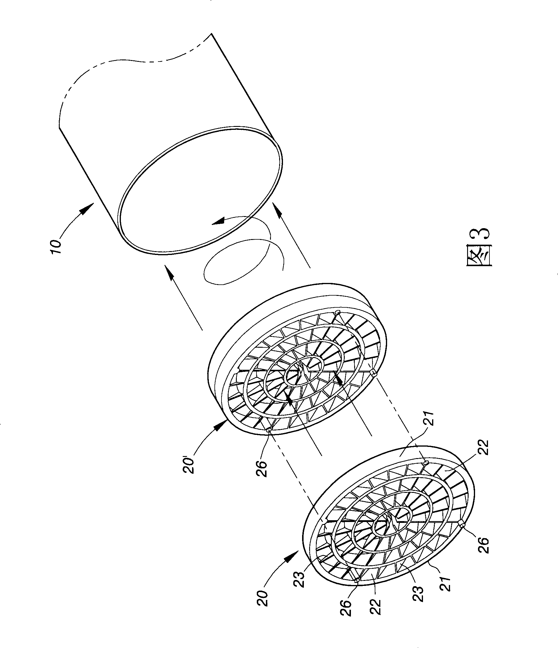
[0027] The above and other technical features and advantages of the present invention will be described in more detail below in conjunction with the accompanying drawings.

[0028] As shown in Figures 3 and 4, the first embodiment of the vehicle engine air intake guide device of the present invention is structured to include at least one main body 20 in the shape of a circular sheet, and a ring 21 is arranged on the outer edge of the main body 20. , the ring 21 can be fixed on the inner edge of the intake pipe 10, and its inner circumference is provided with a plurality of spoiler holes 22, and the plurality of spoiler holes 22 are formed in at least two rows from the inner circumference of the ring 21 to the center point. Grilled, each spoiler hole 22 has at least one piece of spoiler 23 that is inclined to the axial direction of the intake pipe 10 (air intake direction). The plurality of spoiler holes 22 and the spoiler 23 in each spoiler hole 22 can disperse the airflow wit...


PUM


Abstract

The invention discloses an air inflow ducting device for a vehicle engine. The device comprises at least one round sheet-shaped main body with the outer edge provided with a circular ring; the circular ring can be fixed at the inner edge of an air inflow tube, the inner periphery of the circular ring is provided with a plurality of turbulent flow holes, and the plurality of turbulent flow holes are arranged at least in two columns from the inner periphery to the central point of the circular ring so as to form a grille shape; and each turbulent flow hole is internally provided with at least one turbulent flow plate which has a tilting angle relative to the axial direction of the air inflow tube. When the airflow from the intake tube of the vehicle passes the main body, the airflow can be dispersed by the function of the plurality of turbulent flow holes and the turbulent flow plate in each turbulent flow hole, thereby the air inflow tube can intake air uniformly.

Description

technical field [0001] The invention relates to an air guide device, in particular to an air guide device which can be fixed on the inner edge of an air intake pipe. When the airflow from the intake pipe of a vehicle passes through the air guide device, the airflow can be dispersed without concentrating. Background technique [0002] In order to enable the engine to have a better air intake effect at high speeds, there are a variety of spoilers installed on the front end of the intake pipe on the market. The purpose is to make the air in the front end of the engine air intake pipe flow , can produce a swirl flow vortex, this kind of vortex can make the air pass through at a high speed in the form of a vortex when a large amount of air enters the intake pipe. [0003] Such as figure 1 As shown, it is a spoiler structure that has been circulated on the market. The spoiler is installed in the pipeline at the front end of the engine air intake. A central empty pipe 91 with a s...

Claims


Application Information

Patent Timeline
Patent Type & Authority Patents(China)
IPC IPC(8): B60K13/02
Inventor 杨仲玉
Owner 杨仲玉
Learn More