Substrate conveyer

A technology for conveying devices and substrates, which is applied in the direction of conveyor objects, transportation and packaging, furnaces, etc., and can solve the problems that it is difficult to actually use motors and substrates cannot be suspended

Inactive Publication Date: 2010-06-16
SFA ENG CORP
View PDF1 Cites 16 Cited by
  • Summary
  • Abstract
  • Description
  • Claims
  • Application Information

AI Technical Summary

Problems solved by technology

So, if the motor has a large power rating to spray the air that suspends the substrate, it will cause many complications
As a result, it is difficult to practically utilize a mot

Method used


Image

  • Substrate conveyer
  • Substrate conveyer
  • Substrate conveyer

Examples


Embodiment Construction

[0083] For a fuller understanding of the invention and its advantages, reference is made to the accompanying drawings, which illustrate embodiments of the invention.

[0084] Embodiments of the present invention are explained below with reference to the drawings, and the present invention is described in detail. The same reference numerals in the figures denote the same components.

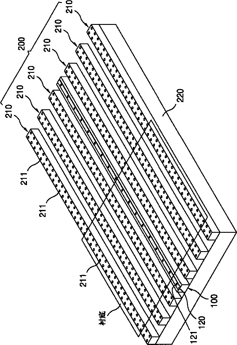
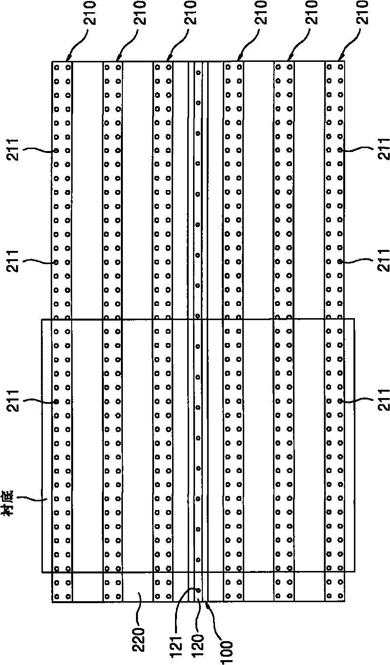
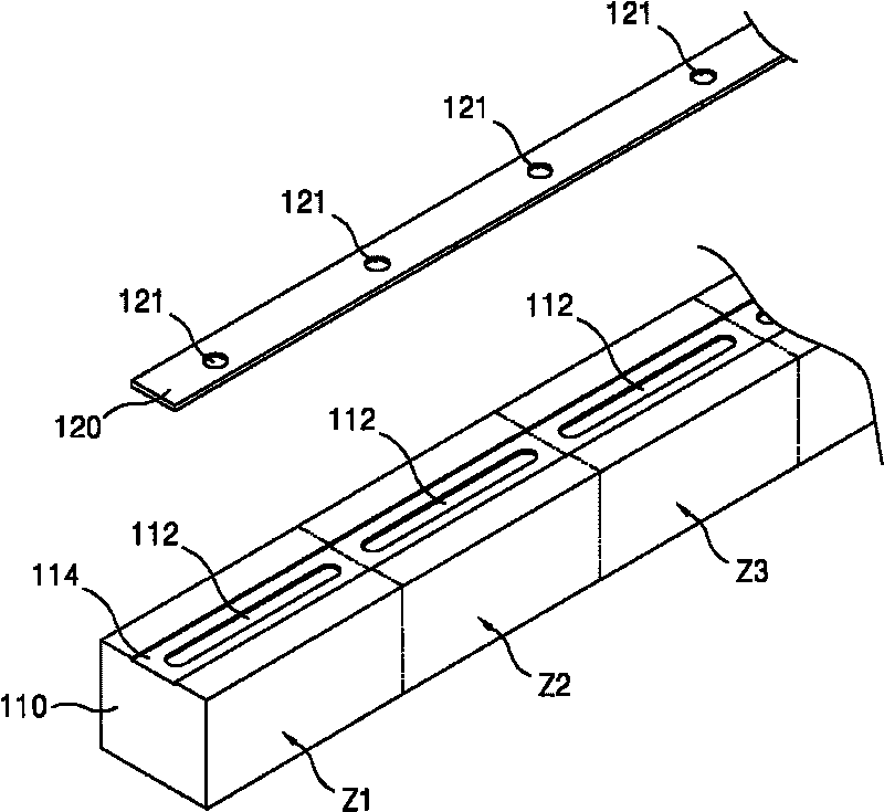
[0085] figure 1 is a perspective view of a substrate transfer device according to a first exemplary embodiment of the present invention; figure 2 for figure 1 floor plan; image 3 is a partially exploded perspective view of the gripping and transporting unit; Figure 4 is a schematic cross-sectional view of the grasping and conveying unit; Figure 5 and Image 6 for figure 1 , showing the operation of the grasping and conveying units, respectively; Figure 7 (a) to (c) schematic representation figure 1 Operation of the substrate transfer device in .

[0086] As shown in the figure, the ...


PUM


Abstract

The invention provides a substrate conveyer, comprising: a grasping and transmitting unit for grasping and arranging at least one area of the substrates parallel to the ground and transmitting the substrates by force application, and an auxiliary transmitting unit adjacent to the grasping and transmitting unit for supporting the transmission of the substrates. Therefore, the structure having moreefficiency than the conventional structure is formed, the conveyer can transmit the substrates at high speed, meanwhile, the noise and the particles can be reduced.

Description

[0001] Cross reference to related applications [0002] This application is claimed based on Korean Patent Application No. 10-2008-0116865 filed with the Korean Intellectual Property Office on November 24, 2008 and Korean Patent Application No. 10-2008-0116866 filed on November 24, 2008 No. and Korean Patent Application No. 10-2009-0055859 filed on June 23, 2009, the entire disclosure of which is incorporated herein by reference. technical field [0003] The invention relates to a substrate transfer device, in particular to a substrate transfer device capable of reducing noise and dust particles, which is more advanced than the traditional structure, and capable of transferring substrates at high speed. Background technique [0004] Generally speaking, the substrate includes: flat panel display (flat panel display; FPD) substrate, such as plasma display panel (plasma display panel; PDP), liquid crystal display (liquid crystal display; LCD), organic light emitting diode (orga...

Claims


Application Information

Patent Timeline
IPC IPC(8): B65G49/06H01L21/677
Inventor 李京南张宰植朴纯弼
Owner SFA ENG CORP
Why Eureka
Try Eureka