Highway-railway dual-purpose box-shaped double-beam T-shaped beam bridge girder erection machine

A road-rail dual-purpose, double-girder technology, applied in the direction of bridges, bridge construction, erection/assembly of bridges, etc., can solve the problem of not really solving R=300m small curved beams, cannot be used to erect railway speed-up T-beams, The problems such as the transverse beam cannot be in place at one time, to achieve the effect of improving work efficiency and operation safety, strengthening wind resistance, and reducing the center of gravity

Active Publication Date: 2010-06-16
ZHENGZHOU NEW DAFANG HEAVY IND & TECH
View PDF0 Cites 27 Cited by
  • Summary
  • Abstract
  • Description
  • Claims
  • Application Information

AI Technical Summary

Problems solved by technology

[0005] 2) Also due to structural weaknesses, the clearance of the middle outrigger frame of the single girder bridge erecting machine is blocked and the structural difficulty of installing the traverse beam mechanism on the single main girder makes it impossible The traversing beam cannot be put in place a

Method used


Image

  • Highway-railway dual-purpose box-shaped double-beam T-shaped beam bridge girder erection machine
  • Highway-railway dual-purpose box-shaped double-beam T-shaped beam bridge girder erection machine
  • Highway-railway dual-purpose box-shaped double-beam T-shaped beam bridge girder erection machine

Examples


Embodiment Construction

[0041] The present invention will be further described below in conjunction with embodiment (accompanying drawing):

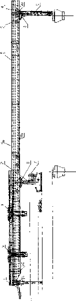
[0042] Such as Figure 1 to Figure 1-4 As shown, the box-shaped double-girder T-girder bridge erecting machine of the present invention comprises a rear leg (1), a middle leg (2), a front leg (3), an auxiliary leg (4), a double main leg Beam (5), front and rear beam trolley (6), electrical and control system (7), front and middle outrigger rollers (8) and hydraulic system (9).

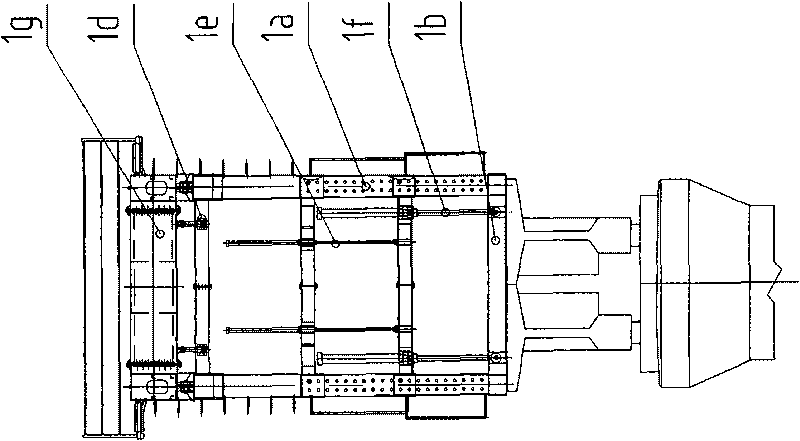
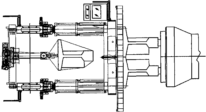
[0043] Such as figure 2 , diagram 2-1 , Figure 2-2 As shown, the middle support leg (2) includes a traversing trolley (2a) that can traverse along the transverse rail (2d), and on the traversing trolley (2a) is a trolley upper turret (2b), (2a) and (2b) are combined through the pivot shaft (2c), and the traversing trolley (2a) and the upper swivel frame (2b) can make relative rotation around the pivot shaft (2c) to adapt to the The need for curved beams; the traversing trolley i...


PUM


Abstract

The invention relates to a highway-railway dual-purpose box-shaped double-beam T-shaped beam bridge girder erection machine, comprising a rear ground jack (1), a middle ground jack (2), a front ground jack (3), an auxiliary ground jack (4), a dual-main beam (5), a front and rear hanging beam trolley (6), an electric appliance and operating system (7), a front and middle ground jack carrier roller (8) and a hydraulic system (9). The bridge girder erection machine has strong adaptability to the technical characteristics of bridges and circuits, thereby having wide popularization and application value. The bridge girder erection machine is suitable for erecting highway T-shape beams and is also suitable for railway T-shape beams.

Description

technical field [0001] The invention relates to bridge erecting equipment, in particular to a box-shaped double-girder T-beam bridge erecting machine suitable for integrally erecting T-shaped prestressed concrete simply supported beams. Background technique [0002] So far, there is no T-shaped girder bridge erecting machine suitable for both road bridges and railway bridges in the world. However, there has been preliminary experience in the use of the single-girder T-beam bridge erecting machine for public and railway use in China, but there has been no publication of the box-shaped double-girder T-beam bridge erection machine for public and railway use. [0003] At present, there are following shortcomings in the existing domestic single-girder T-shaped girder bridge erecting machine for road and railway: [0004] 1) The overall height of the bridge erecting machine is too large and cannot be lowered by itself. The reason is that the operation of feeding and lifting the ...

Claims


Application Information

Patent Timeline
IPC IPC(8): E01D21/00E01D21/08
Inventor 黄耀怡陈浩苏春霞景海州贾力锋陈变玲李淮代宇朱雷鸣康其东刘剑
Owner ZHENGZHOU NEW DAFANG HEAVY IND & TECH
Why Eureka
Try Eureka