Connecting rod type support frame device

A support frame and connecting rod technology, which is applied in the direction of machine/support, supporting machine, instrument, etc., can solve the problems of complicated structure, high cost, complex structure, etc., and achieve the effect of saving material cost.

Active Publication Date: 2011-11-09
JARLLYTEC CO LTD
View PDF1 Cites 0 Cited by
  • Summary
  • Abstract
  • Description
  • Claims
  • Application Information

AI Technical Summary

Problems solved by technology

[0006] Second, the structure is complex and the cost is high:
[0007] The conventional monitor support frame design is too complicated in structure and requires a lot of components. In addition to the high cost, it is not uncommon for parts to fail
[0008] This shows that above-mentioned prior art still has many shortcomings, is not really a good design, and needs to be improved

Method used


Image

  • Connecting rod type support frame device
  • Connecting rod type support frame device
  • Connecting rod type support frame device

Examples


Embodiment Construction

[0029] In order to further understand the features, technical means and the specific functions achieved by the present invention, a more specific preferred embodiment is enumerated, and the detailed description is as follows in conjunction with the accompanying drawings:

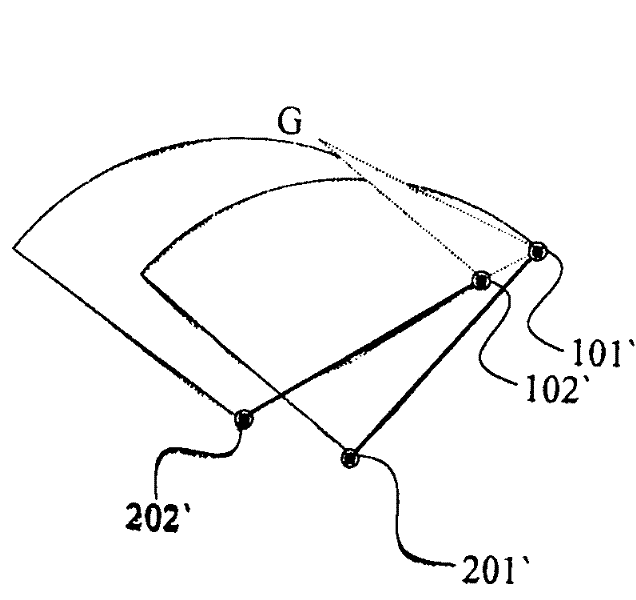
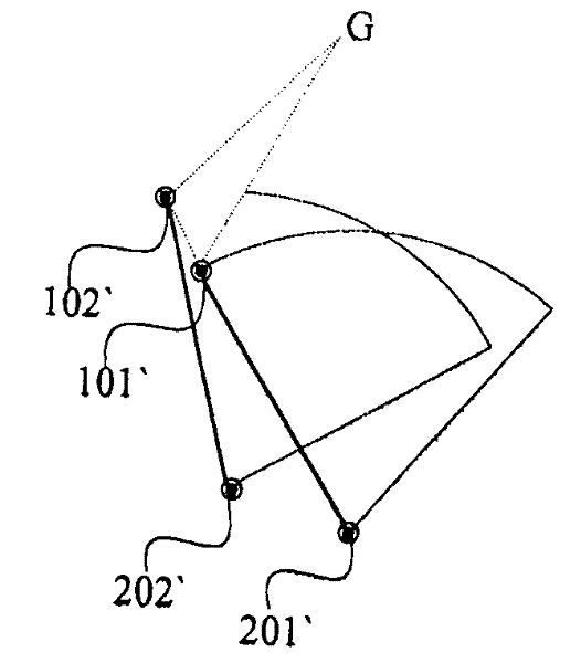
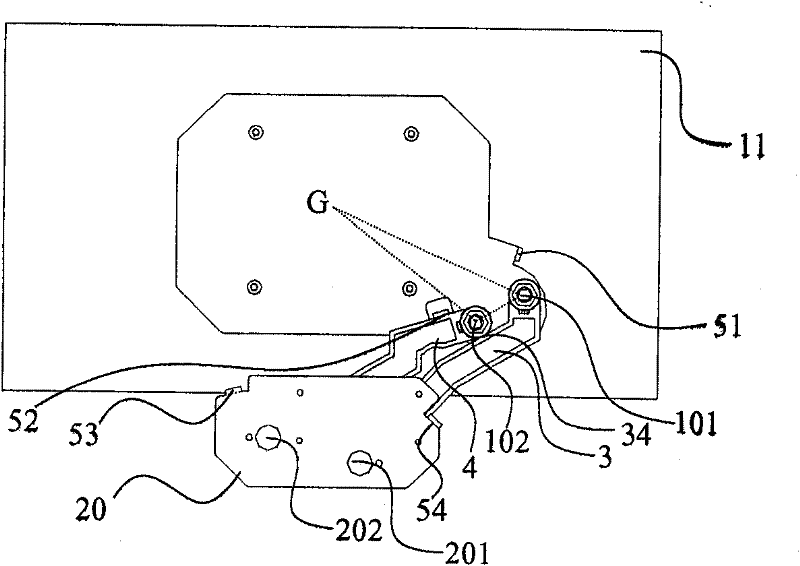
[0030] see figure 1 and figure 2 as shown, figure 1 It is a three-dimensional schematic diagram of a preferred embodiment of the present invention, figure 2 It is a three-dimensional exploded schematic diagram of a preferred embodiment of the present invention. In a preferred embodiment of the present invention, it includes: a base 2, composed of a rotating part 21 and a bottom plate 20, the bottom plate 20 is provided with two given pivot points B201 and a given pivot point D202, and the rotating part 21 can be Adjust the pitch angle of the bottom plate 20 to face. Pivot joints A, B, C and D (symbols 31, 32, 41 and 42) are perforated at the two ends of the first connecting rod 3 and the second connect...


PUM


Abstract

The invention relates to a connecting rod type support frame device comprising two connecting rods with selected lengths, wherein both ends of the connecting rods are respectively pivoted with an electronic device and a base by rotating connection points at different positions. When force is applied to the electronic devices, the electronic devices are turned over to vertical states from horizontal states, two connecting rods are linked with each other so that the central positions of the electronic devices simultaneously rise in the rotating process of the electronic devices, and then the connecting rod type support frame device not only avoids the edges of the electronic devices colliding with tabletops, but also simplifies conventional two stages of firstly rising and then rotating or more motions into a single motion to achieve the purpose. The electronic devices are mainly applied to liquid-crystal displays, organic light-emitting diode (OLED) displays or plasma displays.

Description

technical field [0001] The present invention is a link-type support frame device, especially a kind of pivotal connection between an electronic device and a base using two connecting rods. When the electronic device is rotated, the two connecting rods are linked together so that the electronic device rotates at the same time, and the center of the electronic device The position goes up or down. Background technique [0002] Due to the limited viewing angle of liquid crystal and plasma displays (Plasma Display Panel, PDP), the design of the display base allows users to freely adjust the height, tilt angle and rotate the screen to obtain the best viewing angle. . Known technology such as, on September 1, 2005, the "supporting device with adjustable lifting range and the display module with the supporting device" of Taiwan New Model Patent No. M274544 authorized and announced on September 1, 2005. [0003] However, this customary method has the following disadvantages under t...

Claims


Application Information

Patent Timeline
Patent Type & Authority Patents(China)
IPC IPC(8): F16M11/04G06F1/16
Inventor 许有村
Owner JARLLYTEC CO LTD
Why Eureka
Try Eureka