
Electrical flow distribution mechanism

A flow distribution and electric technology, which is applied in the direction of refrigerators, fluid circulation arrangements, refrigeration components, etc., can solve the problems of increased manufacturing costs, increased control circuits, and complicated pipeline connections, etc., to achieve low manufacturing costs, uniform flow distribution, and manufacturing simple effect

Active Publication Date: 2012-09-05
ZHEJIANG SANHUA INTELLIGENT CONTROLS CO LTD
View PDF2 Cites 0 Cited by
  • Summary
  • Abstract
  • Description
  • Claims
  • Application Information

AI Technical Summary

Problems solved by technology

In this way, the number of components is large, the manufacturing cost is high, and the pipeline connection is relatively complicated. At the same time, due to the corresponding increase in the number of control circuits and valves, the manufacturing cost also increases accordingly.

Method used


Image

  • Electrical flow distribution mechanism
  • Electrical flow distribution mechanism
  • Electrical flow distribution mechanism

Examples


Embodiment Construction

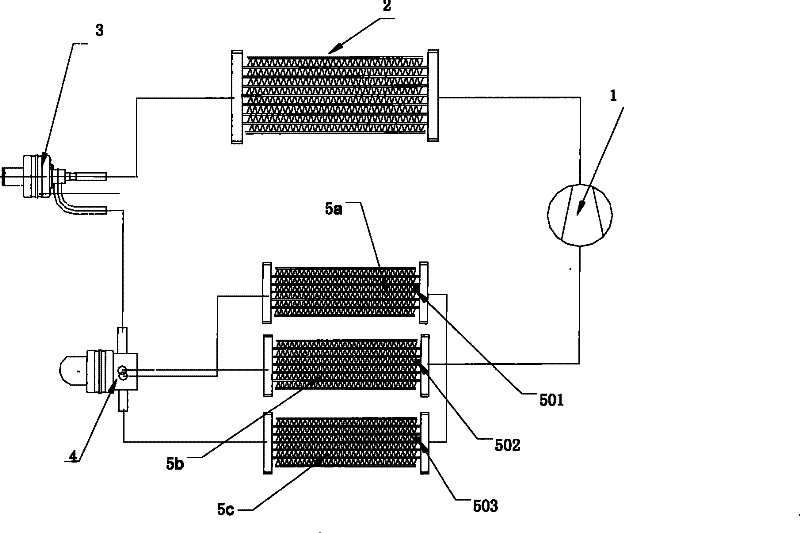
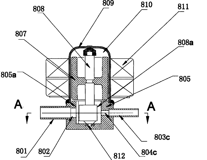
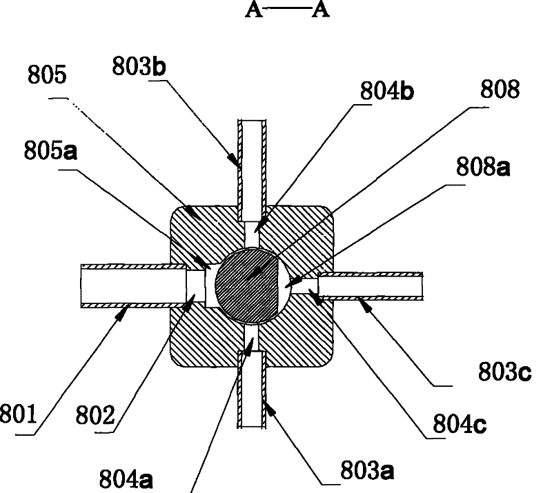
[0025] Embodiments of the present invention will be described in detail below in conjunction with the accompanying drawings. figure 1 It is a schematic diagram of using the electric flow distribution mechanism of the present invention in an air conditioning system. As shown in the figure, the air-conditioning system is a one-to-three inverter air-conditioning system. The air-conditioning system includes an inverter compressor 1, a first heat exchanger 2, an electronic expansion valve 3, an electric flow distribution mechanism 4, three sets of heat exchangers 5a, 5b, 5c are arranged in parallel, and temperature sensors 501, 502, 503 are arranged at the outlets of the three sets of indoor heat exchangers. The three outlets of the electric flow distribution mechanism are respectively connected with three sets of heat exchangers 5a, 5b, 5c, the refrigerant in the air conditioning system is throttled by the electronic expansion valve 3 and then distributed by the electric flow dist...


PUM


Abstract

The invention belongs to an electrical flow distribution mechanism for a refrigerating system, in particular to an electrical flow distribution mechanism for a multi-split air conditioner system or a refrigerating system with a plurality of groups of heat exchangers. The electrical flow distribution mechanism comprises an outer casing, a valve body, an inlet, an inlet connecting pipe, a pluralityof outlets, outlet connecting pipes and a step motor for driving, wherein the inlet connecting pipe is communicated with the inlet; and the outlet connecting pipes are communicated with the outlets. A valve cavity is formed between the valve body and the outer casing. The inlet is communicated with the valve cavity. The outlets are respectively arranged in the circumferential position of the valve body. The flow distribution among the outlets is realized by the step motor driving a shaft to rotate. After the structure is used, the invention has the advantages of small contour, low height, simple structure and low power consumption.

Description

technical field [0001] The invention belongs to an electric flow distribution mechanism for a refrigeration system, in particular to an electric flow distribution mechanism used in a one-to-many air-conditioning system or a refrigeration system with multiple sets of heat exchangers. Background technique [0002] Most air-conditioning systems in the prior art include indoor heat exchangers, outdoor heat exchangers, compressors, and throttling devices. The flow distribution has always been a technical difficulty; many systems use electronic expansion valves to individually control each indoor unit and distribute the flow, as disclosed in the publication of the invention patent application number 200610145015.2 filed on November 29, 2006 The solution is to use a control valve module for each indoor unit to intelligently adjust the electronic expansion valve of each indoor unit, so as to realize the on-demand distribution of the refrigerant flow of one-to-many air conditioners. ...

Claims


Application Information

Patent Timeline
Patent Type & Authority Patents(China)
IPC IPC(8): F25B41/00
Inventor 胡梅宴史初良
Owner ZHEJIANG SANHUA INTELLIGENT CONTROLS CO LTD
Learn More