Distributed fiber sensor for large deformation measurement

A distributed optical fiber, large deformation technology, applied in the direction of optical devices, instruments, measuring devices, etc., can solve the problems that cannot be popularized, small optical fibers, low system range, etc., to achieve large deformation measurement, ensure effective transmission, The effect of improving measurement accuracy

Inactive Publication Date: 2010-06-16
UNIV OF SCI & TECH BEIJING
View PDF0 Cites 21 Cited by
  • Summary
  • Abstract
  • Description
  • Claims
  • Application Information

AI Technical Summary

Problems solved by technology

However, in the current rock and soil deformation monitoring system using distributed optical fibers, the optical fibers that make up the optical fiber line or optical fiber network directly or indirectly bear external deformation, and the optical fiber will produce large deformation, especially when measuring the deformation of rock and soil on a slope. The amount of deformation that the optical fiber itself can withstand is very small, resulting in a low measurement range of the system, which cannot be extended to large deformation geotechnical engineering monitoring

Method used


Image

  • Distributed fiber sensor for large deformation measurement
  • Distributed fiber sensor for large deformation measurement
  • Distributed fiber sensor for large deformation measurement

Examples


Embodiment Construction

[0029] Further illustrate the present invention below in conjunction with accompanying drawing.

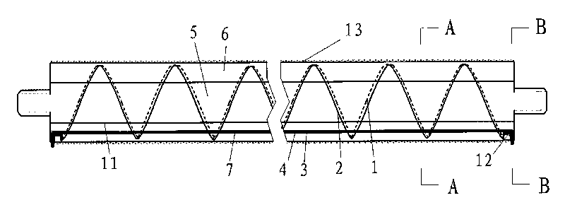
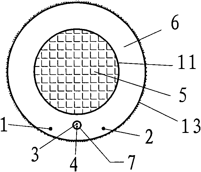
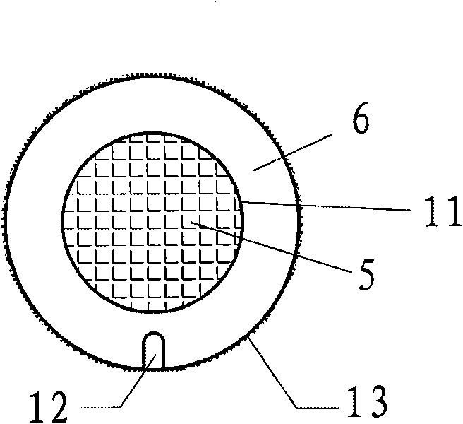
[0030] figure 1 , figure 2 , image 3 It is a vertical section view of the sensor structure and A-A, B-B section views. As shown in the figure, the sensor is mainly composed of an inner metal rod body 5, an outer layer rubber body 6 and four optical fibers. A lubricating layer 11 is provided between the outer layer rubber body 6 and the metal rod body 5 to ensure that the outer layer rubber body and the metal rod Physical energy produces relative motion. The surface 13 of the outer layer of the sensor (rubber body) is rough and can be closely combined with the measured object (such as rock and soil) to form a co-deformable body. The rubber body layer is provided with a reserved hole 7, and the two ends of the rubber body are provided with optical fiber outlets 12. Optical fiber three 3 and optical fiber four 4 in the four optical fibers are temperature correction optical fibe...


PUM


Abstract

The invention relates to a distributed fiber sensor for large deformation measurement, belonging to the field of testing instruments of civil engineering. The main structure of the sensor comprises a metallic rod body and an outer-layer rubber body in which fibers are arranged, wherein a lubricating layer is arranged between the metallic rod body and the outer-layer rubber body; four fibers are arranged in the outer-layer rubber body, wherein two fibers are spirally arranged on the surface layer of the outer-layer rubber body, and the two fibers and the rubber body form an entity and deform together; and simultaneously, a preformed hole is arranged in the outer-layer rubber body, and the other two fibers are arranged in the hole and are connected into a loop for temperature compensation, thereby eliminating the influence of the temperature effect on the measurement result. In the process of measurement, the deformation of the external rock and soil mass causes the outer-layer rubber body of the sensor to deform along the axial direction; and as the fibers for measuring deformation are spirally arranged, only micro deformation is caused along the axial direction of the fibers, thereby realizing large deformation measurement. The sensor can be applied to large deformation measurement of phenomena such as settlement, slippage, delamination and the like of rock and soil mass or structures in the fields of civil engineering, mining engineering and the like, and has the advantages of convenient processing, simple structure and low manufacturing cost.

Description

technical field [0001] The invention belongs to the field of civil engineering testing instruments, and relates to the large deformation measurement of phenomena such as deformation, settlement, slippage and layer separation of rock and soil bodies or structures in geotechnical engineering, slope engineering, and tunnel engineering. Background technique [0002] Most of the stress and deformation monitoring of rock and soil at home and abroad use single-point measurement methods such as inclinometers, pressure gauges and displacement gauges. Due to the complexity of rock and soil deformation, especially the discontinuity of deformation, when When the sensor deforms with the rock and soil as a whole, it cannot obtain real measurement results. At the same time, because the point measurement method cannot realize distributed continuous monitoring, effective and accurate measurement results cannot be obtained. [0003] Distributed optical fiber sensing technology was proposed in...

Claims


Application Information

Patent Timeline
Patent Type & Authority Applications(China)
IPC IPC(8): G01B11/16G02B6/24
Inventor 吴顺川刘洋高利立
Owner UNIV OF SCI & TECH BEIJING
Why Eureka
Try Eureka