Device and method for multi-region dynamically backlight driving

A technology of dynamic backlight and driving method, applied to static indicators, instruments, etc., can solve the problems of increasing difficulty and not being able to effectively solve the mutual influence of light fields

Active Publication Date: 2013-08-07
INNOLUX CORP
View PDF5 Cites 0 Cited by
  • Summary
  • Abstract
  • Description
  • Claims
  • Application Information

AI Technical Summary

Problems solved by technology

However, in figure 2 In the multi-area backlight module structure, although the light blocking units 141, 142 between the backlight sources 121, 122, 123 can reduce the problem of the influence of part of the light field, in fact, because the light has scattering or diffraction In addition, in actual production, the light blocking unit needs to be accurately aligned with the display panel to achieve a good light blocking effect, which also increases the difficulty of production.

Method used


Image

  • Device and method for multi-region dynamically backlight driving
  • Device and method for multi-region dynamically backlight driving
  • Device and method for multi-region dynamically backlight driving

Examples


Embodiment Construction

[0035] In order to improve the color contrast of the display device and reduce the light field interference effect between multiple backlight sources, the present invention proposes a multi-region dynamic backlight driving device and its method. Below, several different implementations of the present invention are provided. form, and accompanied by accompanying drawings to illustrate.

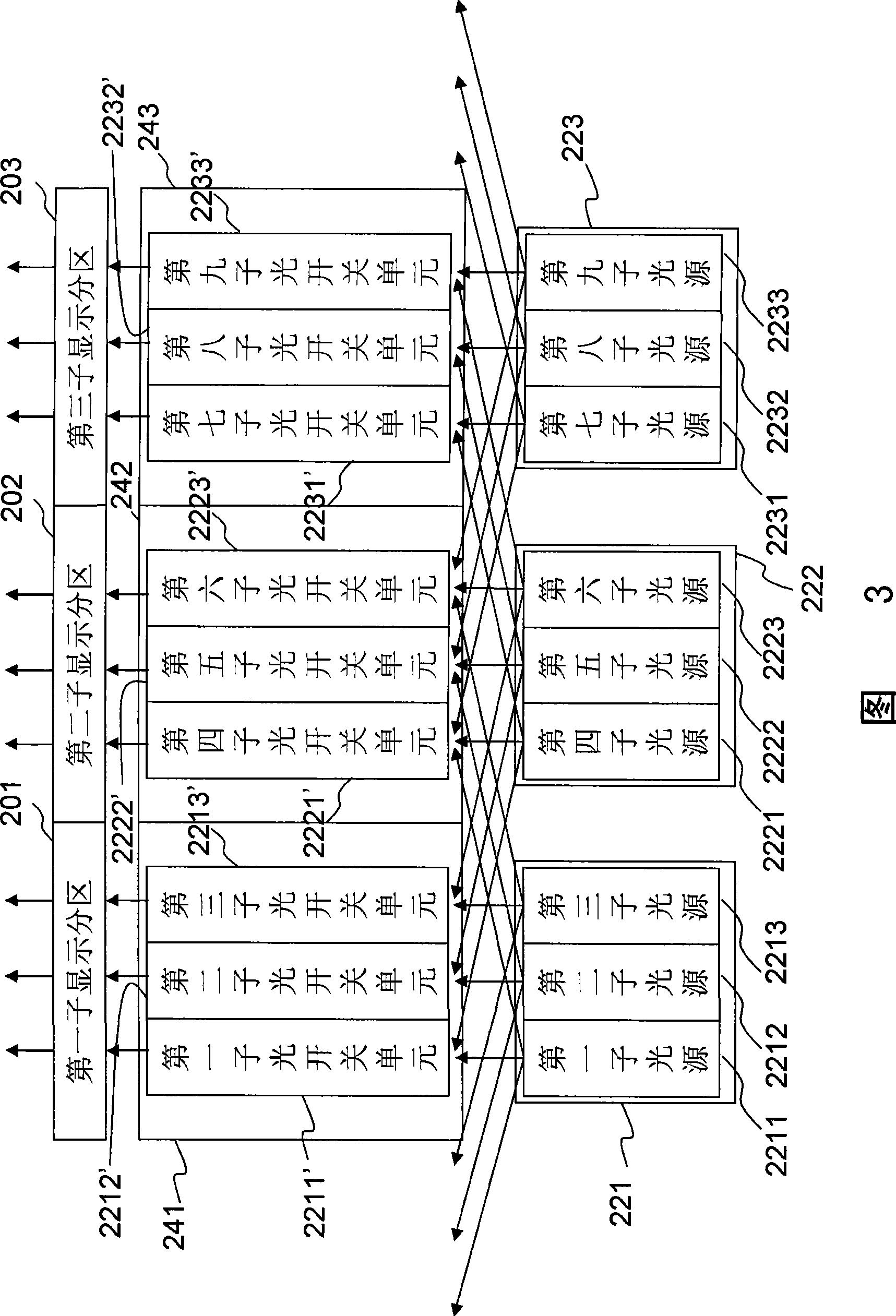
[0036] First, please also refer to image 3 and Figure 4 As shown, among them, image 3 It is a schematic diagram of the device structure of one of the multi-region dynamic backlight driving devices of the present invention, and Figure 4 It is a flow chart of the multi-zone dynamic backlight driving method of the present invention. exist image 3provides a display device with multi-zone dynamic backlight drive, the backlight module of the display device includes a first light source 221, a second light source 222 and a third light source 223, any of the light sources 221, 222 is not limit...


PUM


Abstract

The invention discloses a device and a method for multi-region dynamically backlight driving. Light sources having different colors in each backlight sub-region of different sub-screen time regulating backlight modules and each colorful light switch unit (such as different liquid crystal pixels) are switched on or off in a sub-display sub-region corresponding to a display panel. For instance, when a red light source in a sub-backlight sub-region is switched on, the light source can pass by a red light switch unit on a corresponding sub-display sub-region while the red light switch units in other sub-display sub-regions in other adjacent sub-display sub-regions are switched off, thereby preventing the other adjacent sub-display sub-regions from being affected by the red light source. The method is applied to controlling other color light sources and light switches of the display in order to prevent the display of other adjacent sub-display sub-regions from being interfered by a backlight source corresponding to a specific sub-display region, so the light field disturbing effect between adjacent backlight sources is slight and no light separating unit is needed in the backlight sub-region.

Description

technical field [0001] The present invention relates to a backlight driving device and method thereof, in particular to a multi-region dynamic backlight driving device and method thereof. Background technique [0002] Since the liquid crystal display panel used for imaging in a liquid crystal display device cannot generate light itself, a light source must be provided through a backlight module to present images on the display panel, and as far as known technologies are concerned, the display panel can be It is divided into multiple display areas and each display area has a corresponding backlight. Its purpose is to achieve the effect of inserting a black screen by turning off the backlight in different areas to reduce the image sticking problem that may occur when the liquid crystal display panel displays dynamic images. , or adjust the brightness of the backlight of each partition in accordance with the screens of each display partition to achieve the purpose of saving pow...

Claims


Application Information

Patent Timeline
Patent Type & Authority Patents(China)
IPC IPC(8): G09G3/34G09G3/36
Inventor 杨富吉李嘉航石清文
Owner INNOLUX CORP
Why Eureka
Try Eureka