Method of producing micro-image elements on a substrate

a technology of micro-images and substrates, applied in the field of methods of producing micro-image elements on substrates, can solve the problems of limited resolution and size of micro-images that can be produced by printing methods that cannot be used to produce images requiring a resolution less than approximately 50 microns, limited roll-to-roll gravure printing of high-resolution features, etc., to achieve the effect of increasing the viscosity of lacquer

Active Publication Date: 2021-11-09
CCL SECURE PTY LTD
View PDF8 Cites 0 Cited by
  • Summary
  • Abstract
  • Description
  • Claims
  • Application Information

AI Technical Summary

Benefits of technology

[0014]Three-dimensional microstructures with micron scale (or even sub-micron scale) features can be accurately produced in a relief layer by embossing or related techniques. The inventors have found that a coloured ink fluid applied to a clear or pale relief layer produced in this manner will preferentially accumulate on the three-dimensional microstructures, providing excellent colour contrast between contrasting areas of different ink density. The contrasting areas of different ink density generally comprise areas of high ink density in the regions of high surface curvature on the microstructure units, and contrasting areas of low ink density on adjacent areas of the relief layer. It will be appreciated that the areas of low ink density may be either substantially free of ink, or have a sufficiently low ink density relative to the areas of high ink density that a visible contrast is perceived. Micro-image elements thus formed, which comprise at least ink accumulated in the regions of high surface curvature, may have a higher degree of resolution and reproducibility than can be produced with conventional printing techniques.
[0032]In some embodiments, micro-image elements comprising ink accumulated in the regions of high surface curvature produce a visible optical effect when viewed through an array of focusing elements disposed on the substrate, for example on an opposite surface of the substrate to the relief layer. In some embodiments, the substrate is thus transparent. The visible optical effect may be a magnified moiré image, an integral image, a contrast switching image, an interlaced image, or a flipping image. In some embodiments, the coloured ink fluid forms a design element when directly viewed on the substrate that is distinctive from the visible optical effect.

Problems solved by technology

However, the resolution and size of the micro-images that can be produced by the methods of U.S. Pat. No. 5,712,731 is limited by the reliance on traditional printing methods such as gravure, flexographic and intaglio printing.
Typically, such printing methods cannot be used to produce images requiring a resolution of less than approximately 50 microns.
In particular, roll-to-roll gravure printing of high resolution features is limited by phenomena known in the printing industry as dot skip, drying-in, feathering and screening.
Such phenomena result in defects in printed images, in the form of small missing portions which may be random in their position.
When viewed through an array of micro-lenses, the defects are magnified, producing images that are perceived by the user to have poor quality.
This particularly limits the usefulness of the security features in thin, flexible security documents, such as banknotes or the like.
Apart from aesthetic considerations, poor or inconsistent quality of security features in bank notes may allow counterfeiters the opportunity to pass off poor quality reproductions as genuine bank notes.
However, the colour contrast of such three-dimensional micro-images formed in a monochromatic coating may be unsatisfactory.
However, the magnified image must generally be viewed with point source lighting rather than diffuse lighting due to the diffractive nature of the image elements.
More complex techniques have been reported for producing high resolution micro-images with better colour contrast and which may be viewed in a wide range of lighting conditions.
This technique, while useful for producing high resolution, colour-contrasted micro-images for certain niche applications, is nevertheless difficult to scale up for high throughput production.
Furthermore this multi-step approach suffers from a number of further disadvantages, including the inherent process complexity, the rapid wear imposed on the engraved roller due to ink application and wiping, the impacts on ink adhesion to the substrate due to the pigmentation and pre-curing, and the limitation to a single colour choice per printing unit.

Method used


Image

  • Method of producing micro-image elements on a substrate
  • Method of producing micro-image elements on a substrate
  • Method of producing micro-image elements on a substrate

Examples


example 2

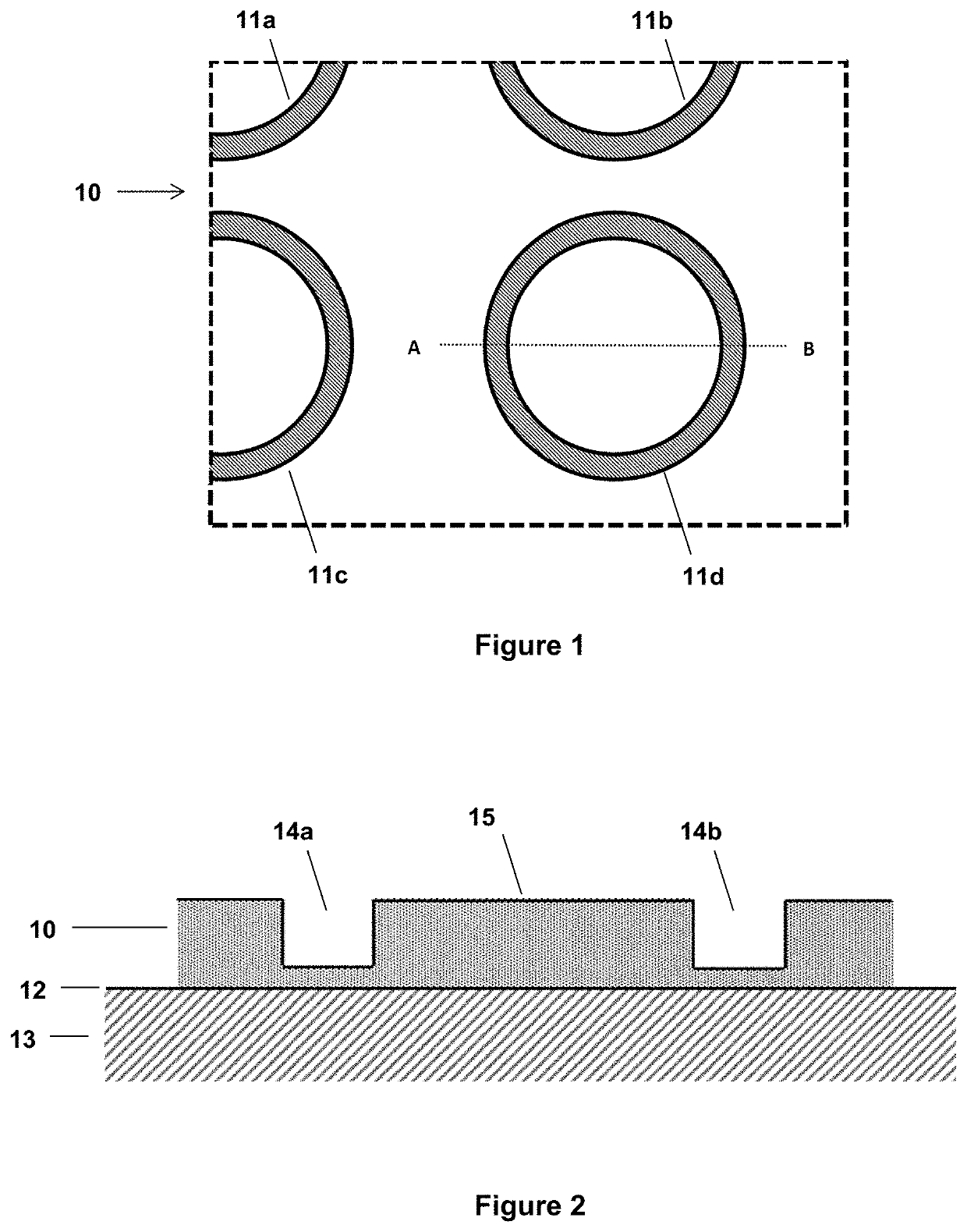
[0131]The embossed relief layer of Example 1 was then overprinted with a silver ink (solvent based, solids content of 30% by volume, application via RK Coater meter bar no. 0). After the ink was dried, yielding a dry loading of 0.2 g / m2, the sheet of micro-lenses was again overlaid on the relief layer, as in Example 1.

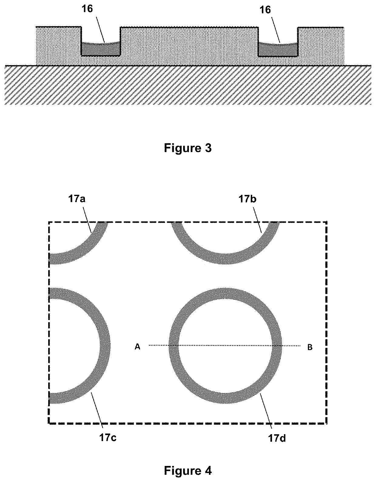
[0132]When viewed through the micro-lenses in transmitted light, an integral image of a magnified “E”-symbol was clearly visible, with excellent contrast. The “E” symbol was approximately 1 cm×1 cm in size, and appeared to float approximately 1 cm above the plane of the micro-lenses. It was evident from the integral image that the ink had accumulated in a substantially uniform distribution on each of the microstructure units, flowing from the immediately surrounding regions of the “E”-shaped microstructure units (which were visibly ink-depleted in the integrated image compared to more distant regions in the base surface plane of the relief layer) into the recessed groo...

example 3

[0133]Another colourless, transparent relief layer comprising microstructure units was produced according to the method of Example 1. In this case, the embossed relief layer comprised an array of microstructure units in the form of “O”-shaped protruding ridges proud on the surface of the relief layer. The embossing height in the relief layer (i.e. the protrusion heights of the embossed features, corresponding to the depth of the recessed embossing elements on the shim) was approximately 1.8 microns. The width of the ridges forming the “O”-shapes was approximately 2 microns.

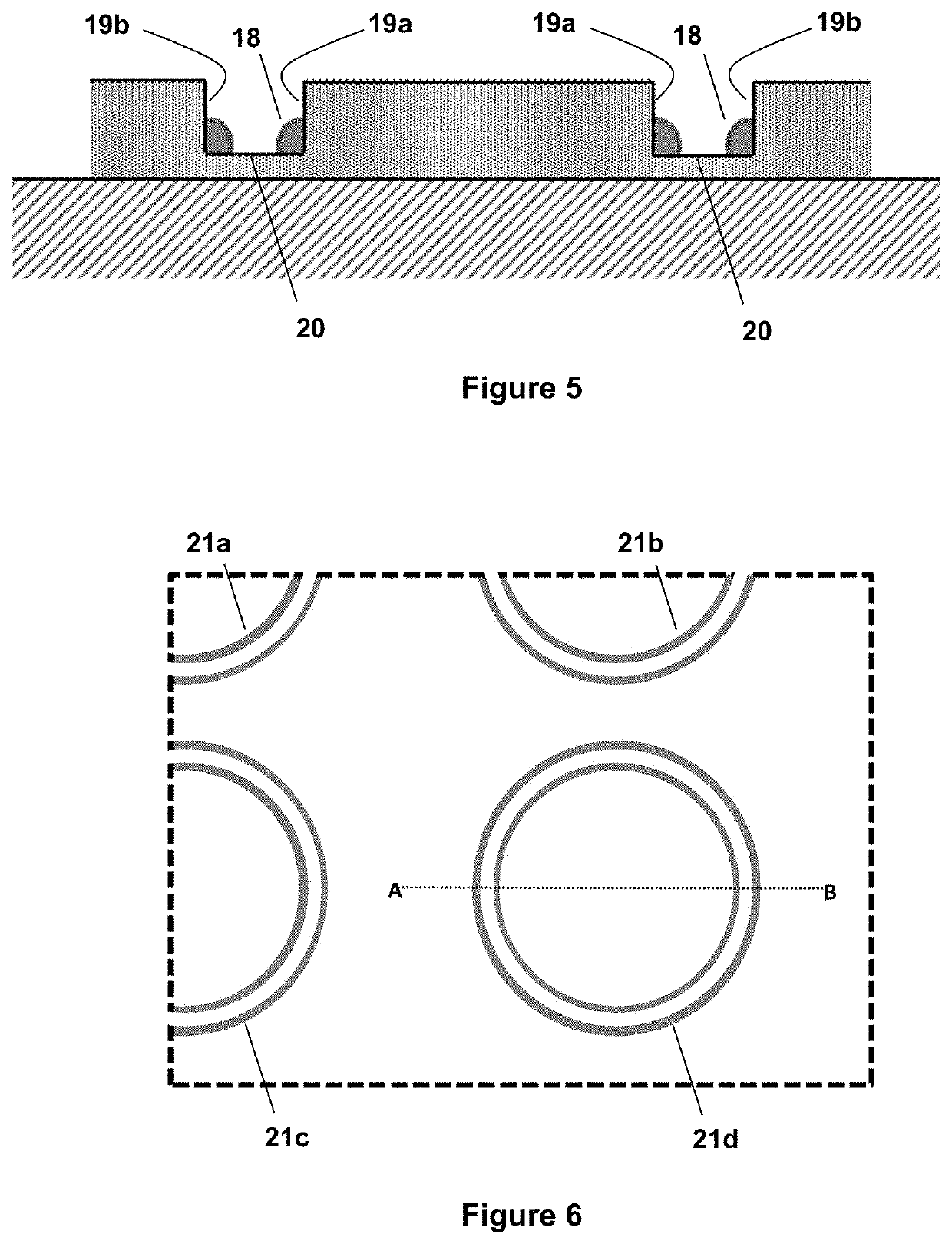
[0134]The embossed relief layer was then overprinted with a silver ink (solvent based, solids content of 30 by volume %, application via RK Coater meter bar no. 0. After the ink was dried in an oven, yielding a dry loading of 0.2 g / m2, the sheet of micro-lenses was again overlaid on the relief layer, as in Example 1.

[0135]When viewed through the micro-lenses in transmitted light, a magnified moiré image of a patte...

example 4

[0136]Another colourless, transparent relief layer comprising microstructure units was produced according to the method of Example 1. In this case, the microstructure units were hexagonally packed unit cells of a repeating hexagon pattern, extending over the surface of the relief layer. The fine lines of the hexagon pattern were recessed grooves embossed into surrounding regions of the relief layer. The hexagonal pattern had a pitch of approximately 53 microns. The embossing depth in the relief layer was approximately 1.7-1.8 microns. The minimum width of the grooves forming the pattern was approximately 1-2 microns.

[0137]The embossed relief layer was then overprinted with a black ink (solvent based, solids content of 20% by volume, viscosity of 19 seconds as measured with a Zahn cup #2; application via RK Coater meter bar no. 0) at a wet loading of 4 g / m2. After the ink was dry, the sheet of micro-lenses was again overlaid on the relief layer, as in Example 1.

[0138]When viewed thro...


PUM

PropertyMeasurementUnit
viscosityaaaaaaaaaa
viscosityaaaaaaaaaa
widthaaaaaaaaaa

Abstract

Embodiments relate to producing micro-image elements on a substrate for a security document, the method comprising: producing a plurality of microstructure units comprising three-dimensionally structured formations in a clear or pale relief layer on the substrate; and applying a coloured ink fluid to the relief layer, wherein the coloured ink fluid accumulates preferentially in regions of high surface curvature on each microstructure unit to provide contrasting areas of different ink density.

Description

CROSS-REFERENCE TO RELATED APPLICATIONS[0001]This application is a bypass continuation application of International Patent Application No. PCT / AU2018 / 050670 filed on Jun. 29, 2018, which claims priority to Australian Patent Application No. 2017902534 filed on Jun. 30, 2017, which are incorporated by reference herein in their entirety.TECHNICAL FIELD[0002]The present invention relates to methods of producing micro-image elements on a substrate for a security document, and to micro-optic devices on a substrate comprising such micro-image elements. In particular, the methods include producing microstructure units comprising three-dimensionally structured formations in a clear or pale relief layer on a substrate, applying a coloured ink fluid to the relief layer, and allowing the coloured ink fluid to accumulate preferentially in regions of high surface curvature on each microstructure unit to provide contrasting areas of different ink density.BACKGROUND OF INVENTION[0003]It is importan...

Claims


Application Information

Patent Timeline
Patent Type & Authority Patents(United States)
IPC IPC(8): B42D25/324B42D25/425B41M3/14
CPCB42D25/324B41M3/142B42D25/425B42D25/30B42D25/40B41M3/14
Inventor JOLIC, KARLO IVANPOWER, GARY FAIRLESS
Owner CCL SECURE PTY LTD
Why Eureka
Try Eureka