Method of determining threshold for detection of peak frequency in radar and object information producing apparatus using the same

a technology of object information and threshold, which is applied in the direction of reradiation, measurement devices, instruments, etc., can solve the problems of large change in the threshold of peak detecting, instability in detecting the target object, and generation of leakage noise, so as to improve the accuracy of producing information and high precision. , the effect of enhancing the accuracy

Active Publication Date: 2012-05-10
DENSO CORP
View PDF7 Cites 23 Cited by
  • Summary
  • Abstract
  • Description
  • Claims
  • Application Information

AI Technical Summary

Benefits of technology

[0013]It is another object to provide an object information producing apparatus designed to ensure enhanced accuracy in producing information about a target object.
[0016]The high-frequency region of the CW noise spectrum where the peak frequency component will not appear, therefore, represents the level of the noise floor of the receiver noise containing the leakage noise, as described above. The use of the high-frequency region of the CW noise spectrum, thus, enhances the accuracy in determining the peak detecting threshold.
[0023]Accordingly, in the high-frequency region, the value of the peak detecting threshold can be determined with high precision by reflecting the receiver noise containing the leakage noise. This results in enhanced accuracy in producing the information about the target object in the high-frequency region (i.e., a middle radar range).
[0024]The object information producing apparatus may also include third analyzing means for deactivating the transmitter while activating the receiver to produce a beat signal as a third beat signal and frequency-analyzing the third beat signal to create a frequency spectrum as a receiver noise spectrum. The threshold determining means adds the 1 / f noise to the receiver noise spectrum in a low-frequency region lower than the CW upper limit component, adjusts a level of the receiver noise spectrum to which the 1 / f noise is added to develop a second distribution successively continuing to the first distribution, and determines the second distribution as a value of the peak detecting threshold in the low-frequency region. This results in enhanced accuracy in creating the peak frequency component in the low-frequency region (i.e., a short radar range), thereby producing the information about the target object correctly in the low-frequency region.

Problems solved by technology

Each of the above techniques is to determine the peak detecting threshold using the results of the frequency analysis from which the peak frequency component is required to be extracted, thus resulting in a great change in the peak detecting threshold with a change in environmental condition, which leads to instability in detecting the target object.
Use of such a type of antenna may result in generation of leakage noise which is too great in level to be ignored as compared with the receiver noise.
Additionally, use of receivers which are lower in receiver noise level for improving the performance of the radar may also cause the level of the leakage noise to be too great to be ignorable relative to the receiver noise.
The above described technique of deactivating the transmitter to measure the noise level has the disadvantage that it is impossible to reflect the effects of the leakage noise on the noise level, thus resulting in a decrease in accuracy in calculating the peak detecting threshold, which leads to inaccuracy in detecting the target object.
It is, therefore, impossible to use the low-frequency region in determining the value of the peak detecting threshold.
When there is a large reflective object in an actual environment, the phase noise-caused lower skirt of the peak frequency component appearing in the low-frequency region of the CW nose spectrum may extend inside the high-frequency region, so that the first distribution, that is, the level of the peak detecting threshold is elevated, thus resulting in deterioration in ability to calculating the border frequency.

Method used


Image

  • Method of determining threshold for detection of peak frequency in radar and object information producing apparatus using the same
  • Method of determining threshold for detection of peak frequency in radar and object information producing apparatus using the same
  • Method of determining threshold for detection of peak frequency in radar and object information producing apparatus using the same

Examples


Embodiment Construction

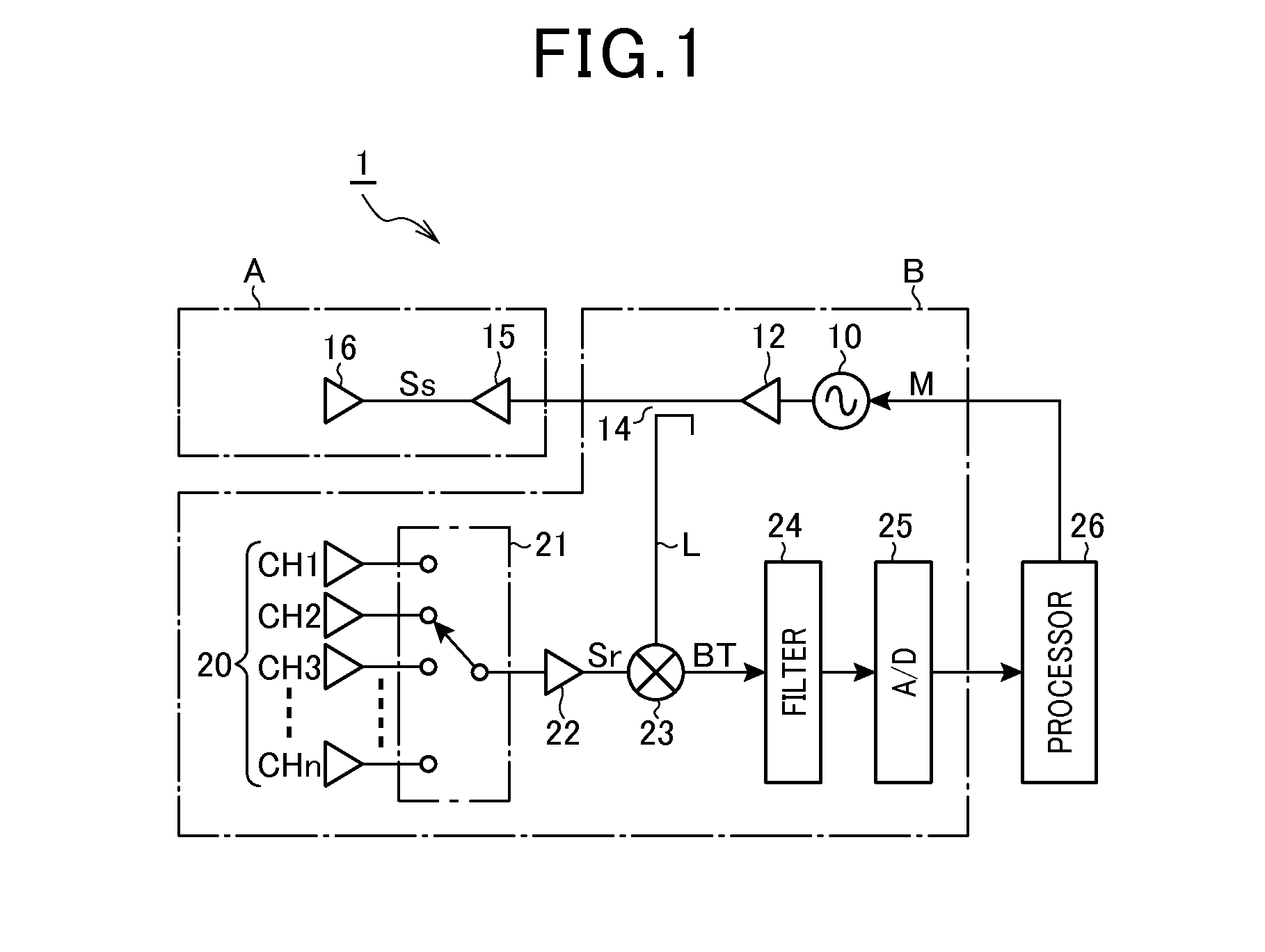
[0046]Referring now to the drawings, particularly to FIG. 1, there is shown a radar system 1 according to the present invention which may be employed in automotive vehicles to detect or track a target object present in a frontal detectable range. The radar system 1 is designed as a FMCW (Frequency Modulated Continuous Wave) type of millimeter-wave radar which transmits a frequency-modulated radar wave in a millimeter band, receives a return thereof, and identifies a target such as a preceding vehicle or a roadside object to produce information about the target.

[0047]The radar system 1 includes an oscillator 10, an amplifier 12, a divider (also called a splitter) 14, an amplifier 15, a transmitter antenna 16, and a receiver antenna assembly 20. The oscillator 10 produces a high-frequency signal in a millimeter band (e.g., 76.5 GHz) and changes an oscillating frequency as a function of the level of a modulation signal M. The amplifier 12 amplifies the high-frequency signal, as produce...


PUM


Abstract

A peak detecting threshold determining method is provided which determines a peak detecting threshold which is used by an FMCW radar in detecting a peak frequency component which appears as representing a target object in a frequency spectrum. A CW radar wave is transmitted to produce a CW noise spectrum. An offset is added to frequency components in a high-frequency region of the CW noise spectrum to define a first distribution as a value of the peak detecting threshold. This enables the value of the peak detecting threshold in the high-frequency region to be determined with high precision by reflecting a receiver noise containing a leakage noise.

Description

CROSS REFERENCE TO RELATED DOCUMENT[0001]The present application claims the benefit of priority of Japanese Patent Application No. 2010-248903 filed on Nov. 5, 2010, the disclosure of which is incorporated herein by reference.BACKGROUND OF THE INVENTION[0002]1. Technical Field[0003]The present invention relates generally to a threshold detecting method which performs frequency analysis (e.g., an FFT algorithm) on a beat signal, as produced in a FMCW (Frequency Modulated Continuous Wave) radar, and determines a threshold value for use in detecting a peak frequency component arising from an echo of a transmitted radar wave from a target object, an object information producing apparatus designed to use the threshold detecting method to produce information about a target object tracked by a radar, and a computer readable program including instructions to perform the threshold detecting method.[0004]2. Background Art[0005]Japanese Patent First Publication No. 11-271431 discloses an FMCW ...

Claims


Application Information

Patent Timeline
Patent Type & Authority Applications(United States)
IPC IPC(8): G01S13/00G01S13/931
CPCG01S7/352G01S13/931G01S13/345G01S7/4056
Inventor ANDO, TAKAMASANATSUME, KAZUMA
Owner DENSO CORP
Why Eureka
Try Eureka