Method for producing a multipole electric motor, and a multipole electric motor

a multi-pole electric motor and electric motor technology, applied in the field of electric motors, can solve the problems of affecting the production efficiency of electric motors, affecting the quality of electric motors, so as to achieve the effect of reducing the cost of producing electric motors according to the invention and positioning particularly accurately

Inactive Publication Date: 2001-02-27
MANNESMANN VDO AG
View PDF8 Cites 23 Cited by
  • Summary
  • Abstract
  • Description
  • Claims
  • Application Information

AI Technical Summary

Benefits of technology

As further advantage, the costs of producing the electric motor according to the invention are reduced when the holding part is constructed as part of a housing of the electric motor.
In accordance with another advantageous feature of the invention, the rotor is positioned particularly accurately with respect to the pole laminations when the holding part has a bearing block for the rotor and / or for a shaft driven by the rotor.

Problems solved by technology

A disadvantage of the known method is that the positioning of the pole laminations with respect to the rotor proves to be very complicated.
Furthermore, even slight deviations of the coils from their prescribed position in the housing lead to a faulty spacing of the pole laminations from the permanent magnet of the rotor.
In the most unfavorable case, the pole laminations can touch the permanent magnet and lead to blocking of the rotor.
As a result, the production of the electric motor proves to be particularly cost-effective.
As a result, however, the sheet-metal part, and thus the bordering regions of the plastic are subjected to a very high thermal load.
The weak laser beam of small diameter leads only to a very slight thermal loading on the sheet-metal part.

Method used


Image

  • Method for producing a multipole electric motor, and a multipole electric motor
  • Method for producing a multipole electric motor, and a multipole electric motor
  • Method for producing a multipole electric motor, and a multipole electric motor

Examples


Embodiment Construction

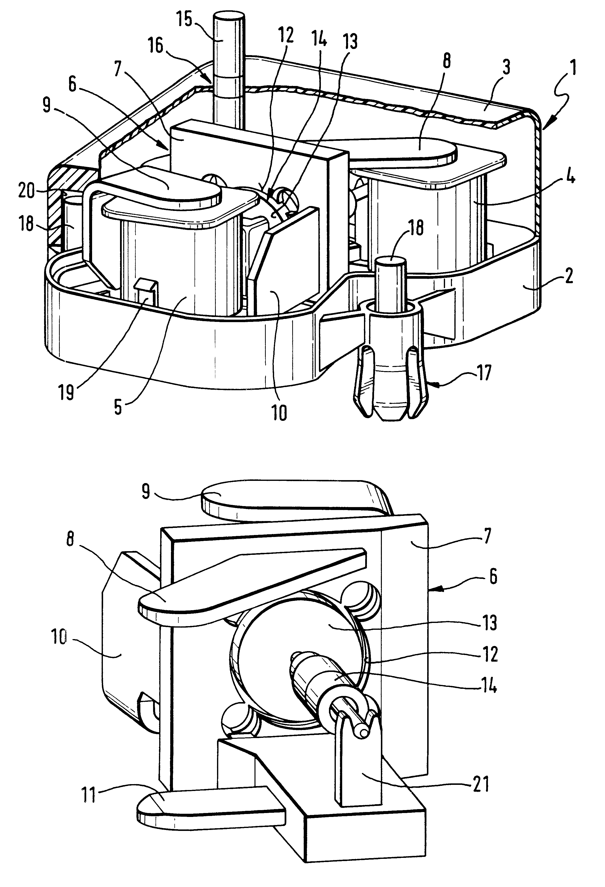
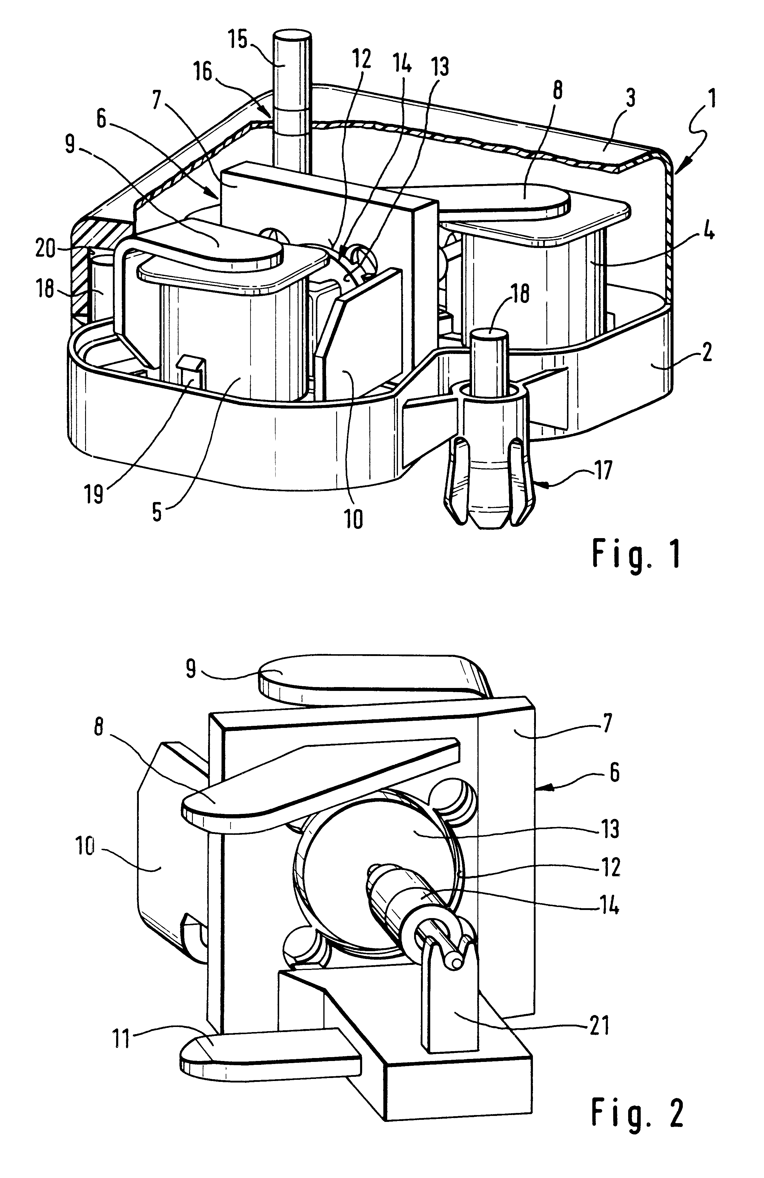
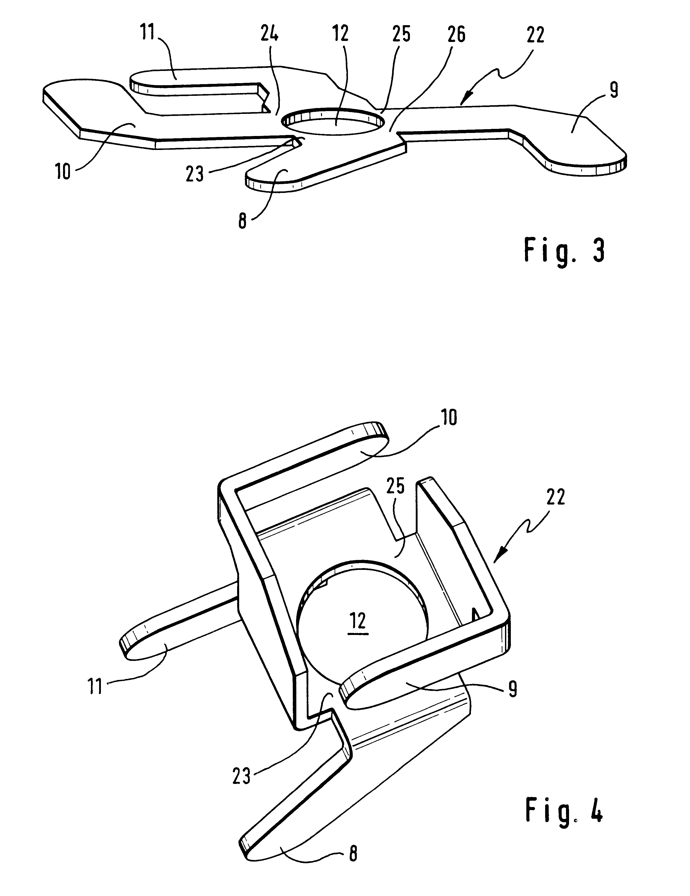
FIG. 1 shows an electric motor according to the invention having a housing 1 which is assembled from a housing lower part 2 and a housing upper part 3. The housing upper part 3 is represented partially cut away in order to clarify the drawing. Two coils 4, 5 and a structural unit 6 composed of a holding part 7 and a total of four pole laminations 8-11 are arranged in the housing 1. The structural unit 6 composed of the holding part 7 and the pole laminations 8-11 has a cutout 12 for holding a multipole permanent magnet 13 of a rotor 14. The pole laminations 8-11 extend in each case from one end of one of the coils 4, 5 to the permanent magnet 13 of the rotor 14, and are bonded to the ends of the coils 4, 5 in order to simplify mounting. The rotor 14 drives a shaft 15, which is guided vertically through the housing upper part 3, via a worm gear (not represented). The housing upper part 3 has a bearing shell 16 in the region of the shaft 15. Arranged on the underside of the housing lo...


PUM


Abstract

A multipole electric motor having a plurality of pole laminations (8-11) guided from ends of coils (4, 5) to a permanent magnet (13) of a rotor (14), the pole laminations (8-11) are firstly produced as a coherent sheet-metal part, and is partially injection-coated with a plastic. Subsequently, the pole laminations (8-11) are separated from one another by means of a laser beam, for example. This renders the mounting of the pole laminations (8-11) particularly simple.

Description

FIELD AND BACKGROUND OF THE INVENTIONThe invention relates to a method for producing a multipole electric motor, in which a plurality of pole laminations mutually separated magnetically are arranged between the ends of coils and a rotor, as well as to a multipole electric motor having a rotor and having a plurality of pole laminations, which are mutually separated magnetically and extend from the ends of coils to the rotor.Such a multipole electric motor and a method for producing it are known in practice. The multipole electric motor has in this case two or more coils as stator and, on the rotor, a cylindrical permanent magnet having a plurality of magnetic poles. One pole lamination is guided in each case from one end of one of the coils to the rotor, where it is situated opposite the permanent magnet with a very slight spacing. In the known method for producing the known electric motor, the pole laminations are individually fastened on the ends of the coils, and the coils are sub...

Claims


Application Information

Patent Timeline
Patent Type & Authority Patents(United States)
IPC IPC(8): H02K1/14H02K15/02H02K21/18H02K21/14
CPCH02K1/14H02K1/143H02K15/022H02K21/18
Inventor SIMON, ERNST-ULRICHKOLIBIUS, HANSZECH, STEFAN
Owner MANNESMANN VDO AG
Why Eureka
Try Eureka