Control device of domestic appliance

A technology for control devices and household appliances, which is applied in household heating, household appliances, and household stoves/stoves. It can solve the problems of high cost, increased user cost, and unsightly appearance, etc., and achieves integrity and ingenious design. Effect

Inactive Publication Date: 2010-06-16
MIDEA GRP CO LTD
View PDF1 Cites 18 Cited by
  • Summary
  • Abstract
  • Description
  • Claims
  • Application Information

AI Technical Summary

Problems solved by technology

However, the traditional knob needs to be connected to the circuit board inside the appliance, so holes need to be opened on the operation panel. This mode is not conducive to waterproofing and cleaning, and the appearance is not beautiful enough.
[0003] Chinese Patent Publication No. CN1685295A discloses an operating unit for household appliances proposed by Siemens, which is a knob for selecting the operating functions of household appliances based on the principle of electromagnetic induction. This patent solves the problem of opening holes on the operating panel , that is, the knob is adsorbed on the panel by magnetic force, but its disadvantage is that the electromagnetic induction needs to use the Hall element to scan the change of the magnetic field, and the knob using the Hall element is more expensive, which increases the user's use cost
In addition, if the knob is accidentally lost or removed, the electrical appliance cannot be operated normally.

Method used


Image

  • Control device of domestic appliance
  • Control device of domestic appliance
  • Control device of domestic appliance

Examples


Embodiment

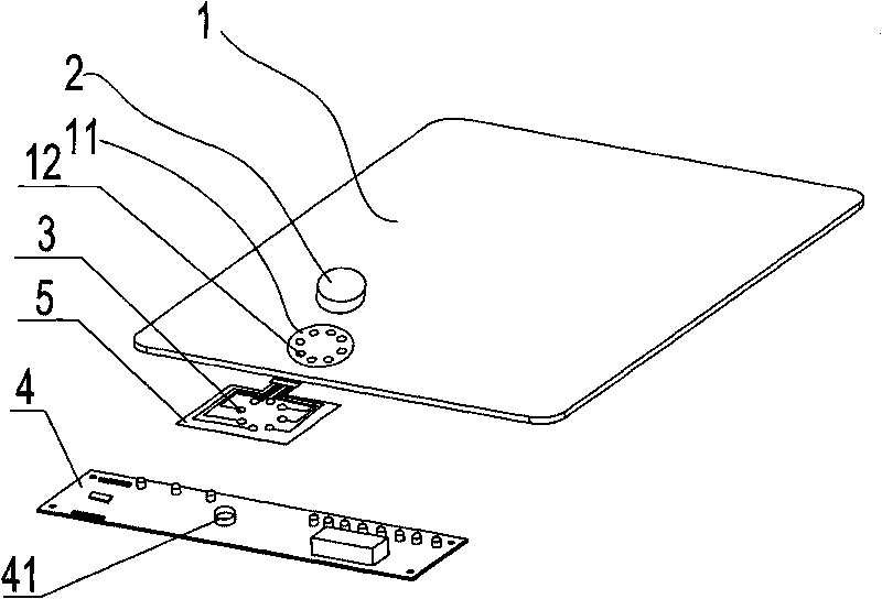
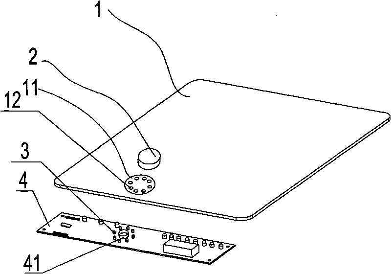
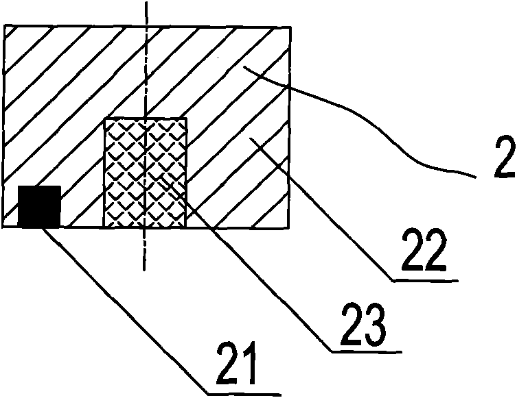
[0019] The structure diagram of the present invention is as figure 1 , 3 , 4, including a panel 1, a knob device 2 installed on the top surface of the panel 1, a touch sensing electrode 3 and a circuit board 4 installed on the bottom surface of the panel 1, wherein the knob device 2 includes a touch sensing component 21, a knob The main body 22 and the fixed part 23, the touch sensing part 21 is arranged on the bottom of the knob main body 22, the fixed part 23 is a permanent magnet, which is installed on the knob main body 22, the circuit board 4 is equipped with a permanent magnet 41, and the knob device 2 passes through it. The fixing part 23 installed on the top and the permanent magnet 41 installed on the circuit board 4 attract each other and are fixed on the panel 1. The touch sensing electrode 3 installed on the bottom surface of the panel 1 and the touch sensing part 21 installed on the bottom of the knob main body 22 corresponding to the position. In this embodimen...

Embodiment 2

[0028] The difference between this embodiment and Embodiment 1 is that the above-mentioned knob device 2 is installed in the operation area 11 on the top surface of the panel 1, and the touch sensing electrode 3 is a traditional spring-type or conductive sponge-type or conductive rubber-type electrode. It is installed on the circuit board 4 at a position corresponding to the upper and lower sides of the operation area 11 .


PUM


Abstract

The invention provides a control device of domestic appliance, which comprises a panel, a knob device arranged on the top face of the panel, a touch-sensitive electrode arranged on the bottom face of the panel and a circuit board, wherein the knob device comprises a touch-sensitive part, a knob body and a fixing part; the touch-sensitive part is arranged at the bottom of the knob body; the fixing part is a permanent magnet and is arranged on the knob body; the circuit board is provided with a permanent magnet; the knob device is fixed on the panel by the attraction between the fixing part arranged on the knob device and the permanent magnet arranged on the circuit board; and the position of the touch-sensitive electrode arranged at the bottom face of the panel corresponds to that of the touch-sensitive part arranged at the bottom of the knob body. The knob device of the invention is fixed on the panel by the attraction between the fixing part arranged on the knob device and the permanent magnet arranged on the circuit board without reserving a hole on a shell of the appliance for mounting the knob device, so the control device keeps the integrity of the appliance, fulfils the aim of preventing water, moisture and creepage, can be operated by a knob and in the way of touch control with fingers and is convenient and practical.

Description

technical field [0001] The invention is a control device of a household appliance, which belongs to the transformation technology of the control device of the household appliance. Background technique [0002] In the existing control devices for household appliances, the operation of the knob is simple, fast, intuitive and flexible, and it is more in line with the operating habits of some users. Therefore, many household appliances will be controlled by knobs. However, the traditional knob needs to be connected to the circuit board inside the appliance, so holes need to be opened on the operation panel. This mode is not conducive to waterproofing and cleaning, and the appearance is not beautiful enough. [0003] Chinese Patent Publication No. CN1685295A discloses an operating unit for household appliances proposed by Siemens, which is a knob for selecting the operating functions of household appliances based on the principle of electromagnetic induction. This patent solves ...

Claims


Application Information

Patent Timeline
Patent Type & Authority Applications(China)
IPC IPC(8): H03K17/95
CPCF24C7/083
Inventor 丁娟毛宏建肖桂良吴志勇任玉洁
Owner MIDEA GRP CO LTD
Why Eureka
Try Eureka