Transmission optimization method, system and equipment of AP network

A technology of network transmission and optimization method, applied in the field of communication, can solve problems such as easy bandwidth, bottleneck, increase transmission delay, etc., to achieve the effect of eliminating bandwidth bottleneck, reducing cost, and optimizing transmission path

Active Publication Date: 2012-08-15
HUAWEI TECH CO LTD
View PDF0 Cites 0 Cited by
  • Summary
  • Abstract
  • Description
  • Claims
  • Application Information

AI Technical Summary

Problems solved by technology

[0004] In the existing technology, the transmission path in the AP network has to go through the core network, which not only increases the transmission delay, but also tends to become a bandwidth bottleneck when the traffic volume of the AG and the core network increases.

Method used


Image

  • Transmission optimization method, system and equipment of AP network
  • Transmission optimization method, system and equipment of AP network
  • Transmission optimization method, system and equipment of AP network

Examples


Embodiment 3

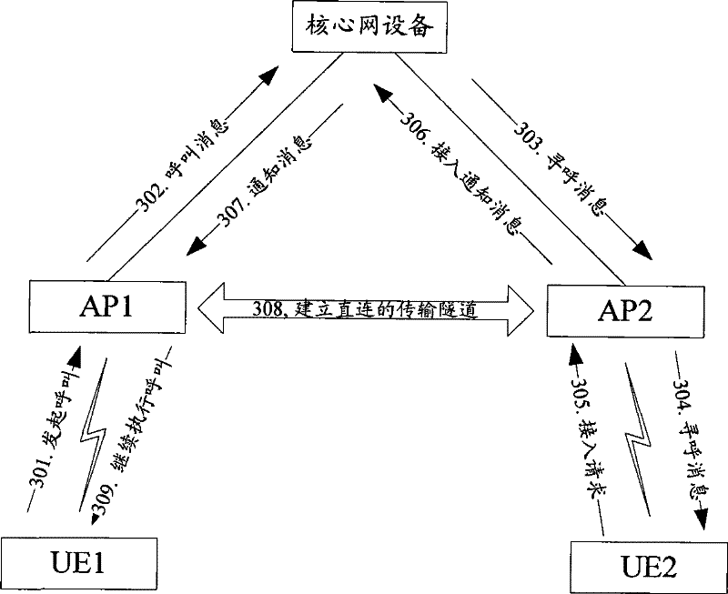
[0087] In the third embodiment of the present invention, AP2 initiates the establishment of a direct connection transmission tunnel, and requires the core network equipment to support the information transfer process of AP1. When UE1 initiates a call to UE2, the information of AP1 is provided to AP2 through the core network equipment (AG or CN). direct transmission channel. Specific process such as Figure 5 shown, including the following steps:

[0088] Step 501, UE1 initiates a call message to UE2;

[0089] Step 502, AP1 uploads the call message to the core network device, and the call message carries AP1 information;

[0090] Step 503, the core network device sends a paging message to AP2 to page UE2, and the paging message carries AP1 information; of course, if there is no AP1 information in the paging message in step 502, the core network device can also pre-store Fill in the relevant communication address of AP1 in the paging message;

[0091] Step 504, AP2 sends a ...


PUM


Abstract

The embodiment of the invention discloses a transmission optimization method of an AP network, a first access point receives a call message sent to a second user by a first user; the first access point acquires the communication address of a second access point belonging to the second user; and the first access point establishes a direct-connecting transmission tunnel between the first access point and the second access point to enable the first user to communicate with the second user by the direct-connecting tunnel. In the embodiment of the invention, the transmission path of the AP networkcan be optimized, the transmission delay is improved, the bandwidth bottleneck of a core network is eliminated and meanwhile, the cost of the core network is lowered.

Description

technical field [0001] The present invention relates to the field of communication technology, in particular to an AP network transmission optimization method, system and equipment. Background technique [0002] The user plane data flow of the existing AP (Access Point, access point) network is as follows: figure 1 As shown, all services must pass through the core network. For example, when two UEs (User Equipment, user equipment) performing services are under the AP, the transmission path between the two UEs is AP->IP network->switching equipment->AG (Access Gateway, access gateway )->MSC / SGSN (Serving GPRS Support Node, serving GPRS support node), GGSN (Gateway GPRS Support Node, gateway GPRS support node)->AG->switching device->IP network->AP. [0003] In the process of realizing the present invention, the inventor finds that there are at least the following problems in the prior art: [0004] In the prior art, the transmission path in the AP netwo...

Claims


Application Information

Patent Timeline
Patent Type & Authority Patents(China)
IPC IPC(8): H04W76/02H04W74/00
Inventor 吴健
Owner HUAWEI TECH CO LTD
Why Eureka
Try Eureka