Impulse light-regulation circuit and impulse light-regulation method

A pulse dimming and circuit technology, which is applied in the field of pulse dimming circuits and pulse dimming, can solve problems such as high cost and inconvenience

Active Publication Date: 2013-08-28
CHENGDU MONOLITHIC POWER SYST
View PDF3 Cites 1 Cited by
  • Summary
  • Abstract
  • Description
  • Claims
  • Application Information

AI Technical Summary

Problems solved by technology

The current solution often uses two circuit boards, each for a dimming method, but this is costly and inconvenient

Method used


Image

  • Impulse light-regulation circuit and impulse light-regulation method
  • Impulse light-regulation circuit and impulse light-regulation method
  • Impulse light-regulation circuit and impulse light-regulation method

Examples


Embodiment Construction

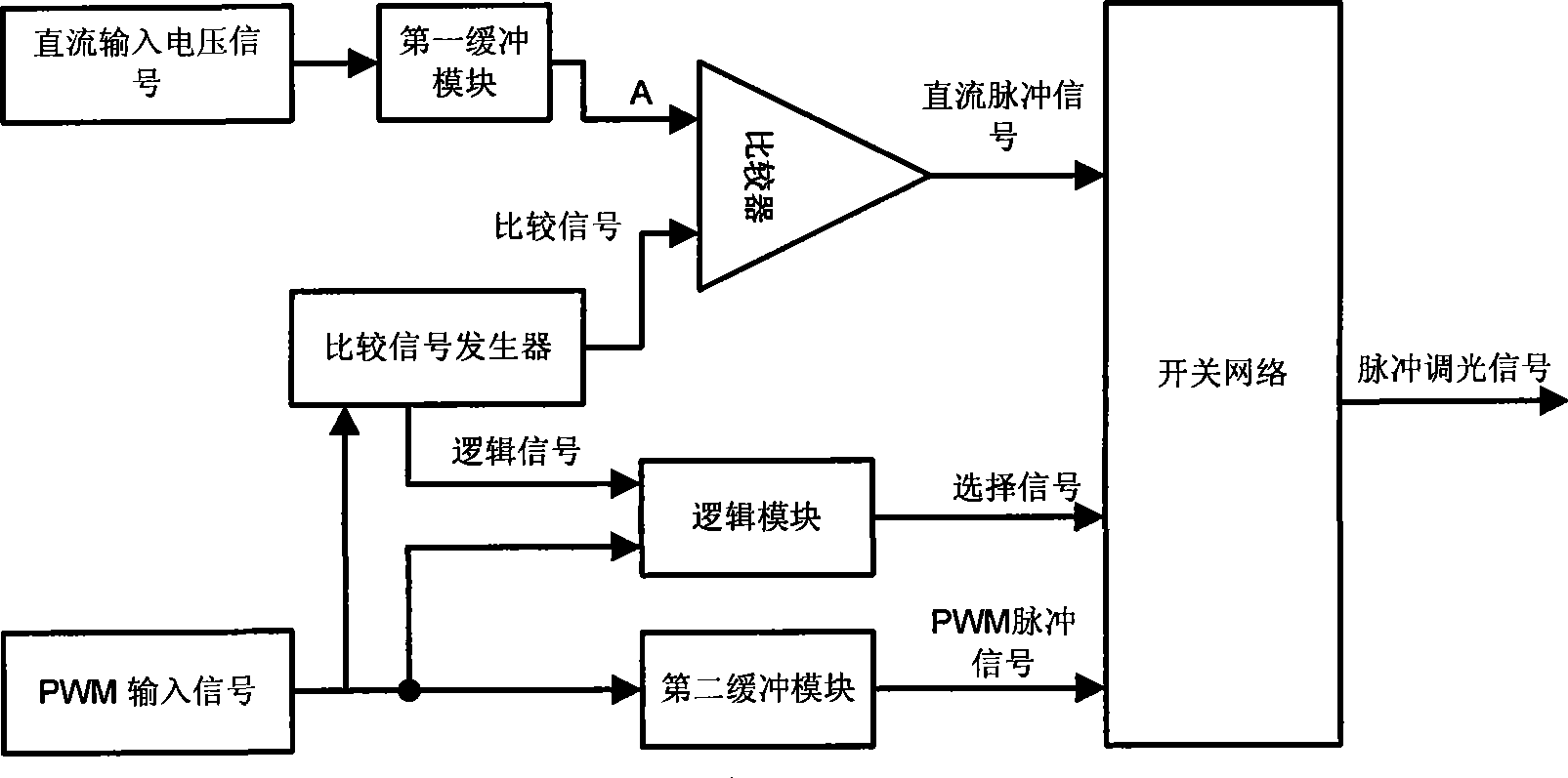
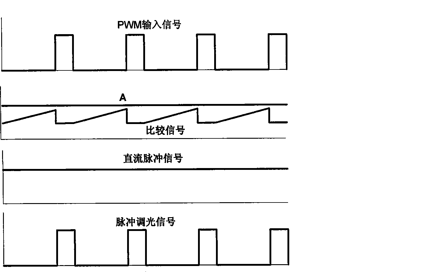
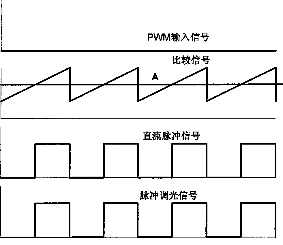
[0034] figure 1 It is a schematic diagram of a pulse dimming circuit according to an embodiment of the present invention. The pulse dimming circuit mainly includes: a first input port, a second input port, a comparison signal generator, a comparator, a logic module and a switch network, wherein the first input port is used for coupling connected to the DC input voltage signal; the second input port is used to couple the PWM input signal when the PWM input signal is input; it is used to generate the first / second comparison signal input to the comparator, and identify whether If the PWM input signal is input, if so, output the first comparison signal to the comparator, and output the first logic signal to the logic module; otherwise, output the second comparison signal to the comparator, and output the first Two logic signals are sent to the logic module; a comparator is used to compare the DC input voltage signal and the second comparison signal, and output a DC pulse signal t...


PUM


Abstract

The present invention provides a pulse dimming circuit and a method thereof. The pulse dimming circuit is compatible for both DC input signal and PWM input signal using only one circuit board, and includes a first input port, a second input port, a comparison signal generator, a comparator, a logic module, and a switch network electrically coupled to the second input port, an output terminal of the comparator, and an output terminal of the logic module.

Description

technical field [0001] The invention relates to a dimming circuit and a method thereof for a cold cathode fluorescent lamp, in particular to a pulse dimming circuit and a pulse dimming method. Background technique [0002] The inverter of cathode fluorescent lamp (CCFL) often adopts pulse dimming, and there are usually two pulse dimming methods, that is, pulse dimming using DC input voltage and pulse dimming using external PWM input signal. For the pulse dimming method of DC input, it is necessary to compare the wave generator component, and generate the pulse signal for pulse dimming by comparing the DC input level with the comparative wave; and for the pulse dimming method using PWM input signal That said, the pulse dimming signal directly follows the PWM input signal, so no comparator wave generator components are required. Therefore, the two pulse dimming methods are not compatible with each other. Circuits for pulse dimming with DC input are not suitable for pulse dim...

Claims


Application Information

Patent Timeline
Patent Type & Authority Patents(China)
IPC IPC(8): H05B41/38
CPCH05B41/282Y02B20/183Y02B20/00
Inventor 刘白仁杜磊任远程
Owner CHENGDU MONOLITHIC POWER SYST
Why Eureka
Try Eureka