Photoelectric signal receiving method for realizing self-adaptive switching of sampling resistance values

A technology of self-adaptive switching and sampling resistance, which can be used in self-adaptive network, photometry, and photometry using electrical radiation detectors. It can solve the problem that the photoelectric signal receiving method cannot accept photoelectric signals.

Inactive Publication Date: 2021-04-30
无锡芯明圆微电子有限公司
View PDF1 Cites 0 Cited by
  • Summary
  • Abstract
  • Description
  • Claims
  • Application Information

AI Technical Summary

Problems solved by technology

[0004] The existing photoelectric signal receiving method cannot accept photoelectric signals with a large dynamic range, so it is necessary to use a dedicated chip for receiving and processing infrared light signals with photosensitive diodes, so as to realize the photoelectric signal receiving method of adaptively switching the sampling resistance value

Method used


Image

  • Photoelectric signal receiving method for realizing self-adaptive switching of sampling resistance values
  • Photoelectric signal receiving method for realizing self-adaptive switching of sampling resistance values
  • Photoelectric signal receiving method for realizing self-adaptive switching of sampling resistance values

Examples


Embodiment 1

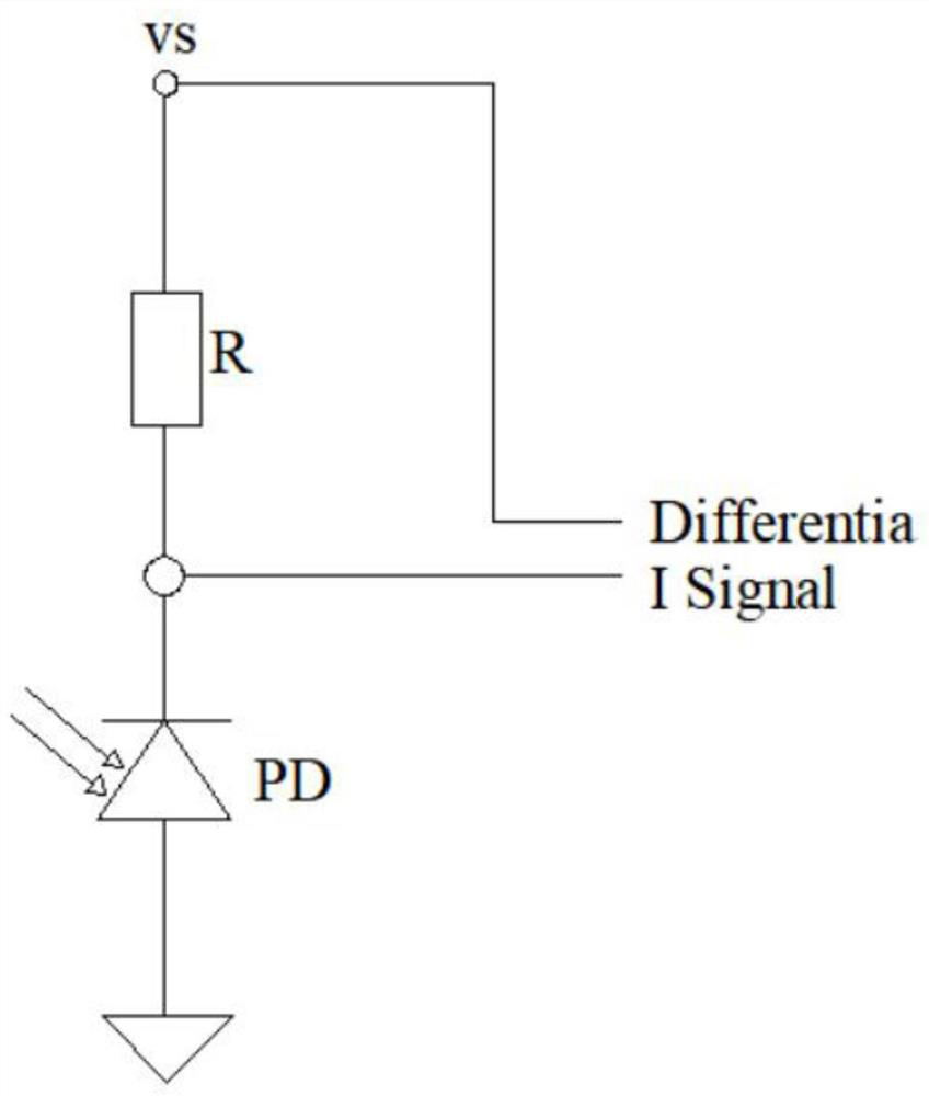
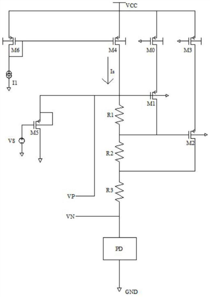
[0032] refer to Figure 1-3 , to realize the photoelectric signal receiving method of adaptively switching the sampling resistance value, including sampling resistance, voltage source, photosensitive diode, PMOS tube and NMOS tube, the photosensitive diode will generate different currents with the intensity of the incident infrared light signal, and the photosensitive diode will generate The different currents are connected to the voltage source through the sampling resistor, the voltage source is defined as VS, the photosensitive diode is PD, the PMOS tube includes M4, M5 and M6, the NMOS tube includes M1 and M2, and the PMOS tube and NMOS tube are connected to the voltage source. The sampling resistor includes R1, R2 and R3, and the specific photoelectric signal receiving method includes the following steps:

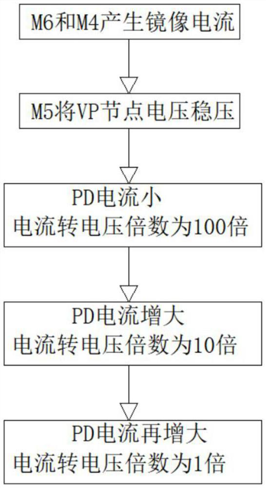
[0033] S1: The current mirror composed of PMOS transistors M6 and M4 generates mirror current;

[0034] S2: The reference voltage is the voltage source, and the VP no...

Embodiment 2

[0047] refer to Figure 1-3 , to realize the photoelectric signal receiving method of adaptively switching the sampling resistance value, including sampling resistance, voltage source, photosensitive diode, PMOS tube and NMOS tube, the photosensitive diode will generate different currents with the intensity of the incident infrared light signal, and the photosensitive diode will generate The different currents are connected to the voltage source through the sampling resistor, the voltage source is defined as VS, the photosensitive diode is PD, the PMOS tube includes M4, M5 and M6, the NMOS tube includes M1 and M2, and the PMOS tube and NMOS tube are connected to the voltage source. The sampling resistor includes R1, R2 and R3, and the specific photoelectric signal receiving method includes the following steps:

[0048] S1: The current mirror composed of PMOS transistors M6 and M4 generates mirror current;

[0049] S2: The reference voltage is the voltage source, and the VP no...

Embodiment 3

[0062] refer to Figure 1-3 , to realize the photoelectric signal receiving method of adaptively switching the sampling resistance value, including sampling resistance, voltage source, photosensitive diode, PMOS tube and NMOS tube, the photosensitive diode will generate different currents with the intensity of the incident infrared light signal, and the photosensitive diode will generate The different currents are connected to the voltage source through the sampling resistor, the voltage source is defined as VS, the photosensitive diode is PD, the PMOS tube includes M4, M5 and M6, the NMOS tube includes M1 and M2, and the PMOS tube and NMOS tube are connected to the voltage source. The sampling resistor includes R1, R2 and R3, and the specific photoelectric signal receiving method includes the following steps:

[0063] S1: The current mirror composed of PMOS transistors M6 and M4 generates mirror current;

[0064] S2: The reference voltage is the voltage source, and the VP no...


PUM


Abstract

The invention belongs to the technical field of photoelectric receiving, particularly relates to a photoelectric signal receiving method for realizing self-adaptive switching of sampling resistance values. Aiming at the problem that a large optical signal receiving range cannot be met, the following scheme is provided, namely, the method comprises the following steps of: S1, PMOS (P-channel Metal Oxide Semiconductor) tubes M6 and M4 generate a mirror current; S2, a PMOS tube M5 stabilizes the voltage of a VP node at a fixed value; S3, when the current of a photosensitive diode is very small, the sampling resistance value is 100 * r0, and the current-to-voltage amplification factor is 100; S4, when the current of the photosensitive diode is increased, the node voltage clamping value of the source end of an NMOS tube M1 is VS + Vt5 - Vt1, and the current-to-voltage amplification factor is 10; and S5, when the current of the photosensitive diode is increased again, the node voltage clamping value of the source end of the NMOS tube M2 is VS + Vt5 - Vt1 - Vt2, and the current-to-voltage amplification factor is 1. According to the invention, good signal receiving under strong light irradiation and sensitive receiving of weak infrared light signals can be realized, and the requirement of large dynamic range of light signals received by a photosensitive diode is met.

Description

technical field [0001] The invention relates to the field of photoelectric reception, in particular to a photoelectric signal receiving method for realizing self-adaptive switching of sampling resistance values. Background technique [0002] The sampling resistor is used for current sampling and voltage sampling. For current sampling, a resistor with a small resistance value is connected in series, and for voltage sampling, a resistor with a large resistance value is connected in parallel. This type of resistor is divided according to the function of the product. The function of the sampling resistor is used as a reference. It is often used in the feedback circuit. Taking the regulated power supply circuit as an example, in order to keep the output voltage constant, a part of the voltage should be taken as a reference from the output voltage (commonly used in the form of a sampling resistor). If When the output is high, the input terminal will automatically reduce the volta...

Claims


Application Information

Patent Timeline
Patent Type & Authority Applications(China)
IPC IPC(8): G01J1/44H03H21/00H03K17/687
CPCG01J1/44H03H21/00H03K17/687G01J2001/446G01J2001/4406
Inventor 杨明
Owner 无锡芯明圆微电子有限公司
Why Eureka
Try Eureka