Throttle on a valve needle of a fuel injection valve for internal combustion engines

A technology of fuel injection valve and internal combustion engine, which is applied in the direction of fuel injection valve, fuel injection device, special fuel injection device driven by fluid pressure, etc., can solve the problem of inaccurate emission of harmful substances, loss of system efficiency, and viscosity of throttling action. and other problems, to achieve the effect of fast closing and ensuring irrelevance

Active Publication Date: 2010-06-16
ROBERT BOSCH GMBH
View PDF9 Cites 7 Cited by
  • Summary
  • Abstract
  • Description
  • Claims
  • Application Information

AI Technical Summary

Problems solved by technology

However, such a low-pressure stage has the disadvantage that it leads to high leakage and thus requires a higher pump power, which leads to a loss of system efficiency and thus to higher fuel consumption
However, the following problem arises here: the throttling effect is related to the viscosity of the fuel, which in turn is a function of pressure and temperature
The resulting inaccuracies in the measurement of the fuel quantity have a negative effect on the pollutant emissions of the internal combustion engine

Method used


Image

  • Throttle on a valve needle of a fuel injection valve for internal combustion engines
  • Throttle on a valve needle of a fuel injection valve for internal combustion engines
  • Throttle on a valve needle of a fuel injection valve for internal combustion engines

Examples


Embodiment Construction

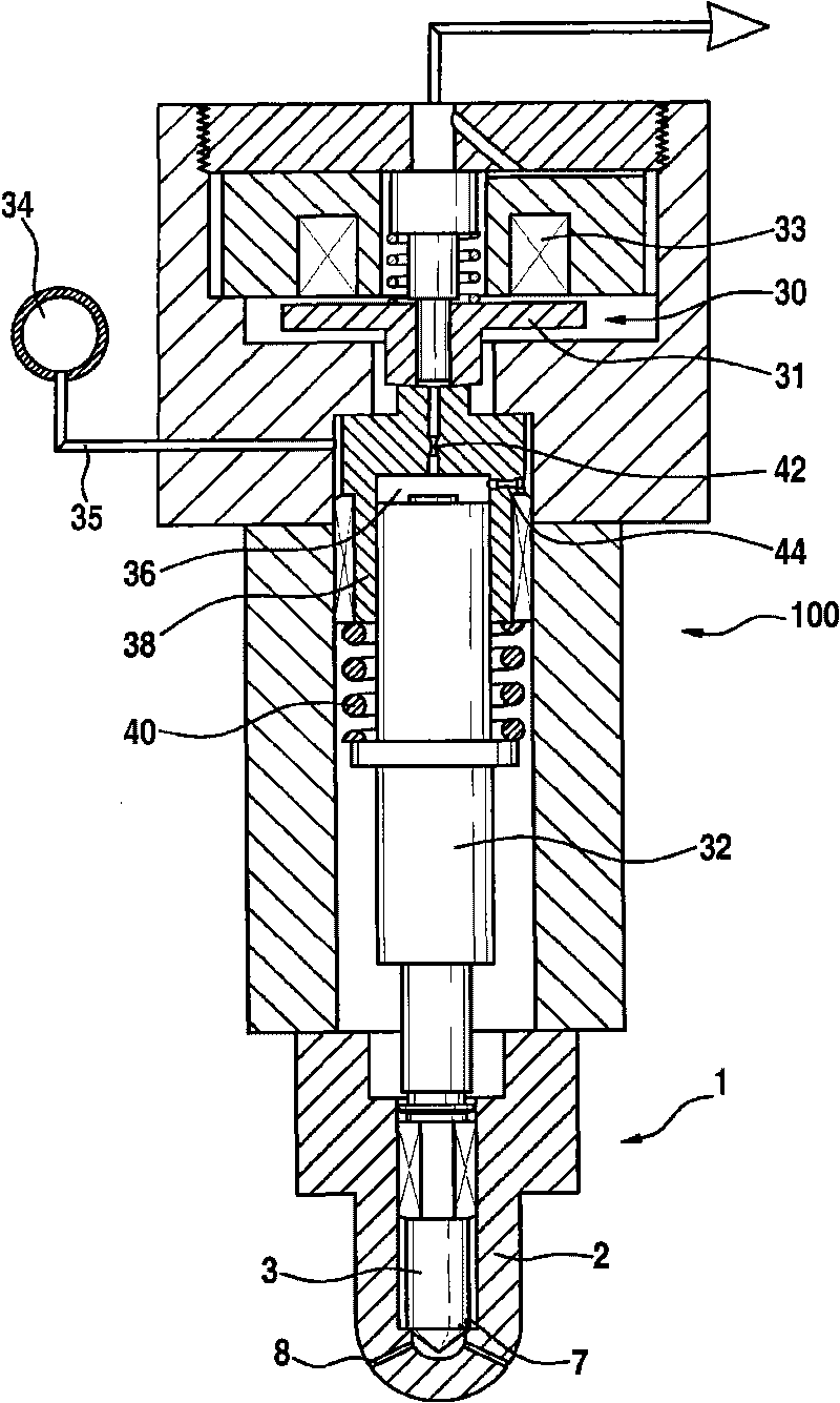
[0013] figure 1 A fuel injection valve is shown in longitudinal section. The basic principles of such fuel injection valves are already known from the prior art, so that a detailed description of known components can be omitted and only a brief description of their function follows. The fuel injector comprises a fuel injection valve 1 and an injector body 100 including a control valve 30 for controlling injection. The injector body 100 is connected to a fuel injection valve 1 , which comprises a valve body 2 and in which an injection hole 8 is arranged, through which fuel is injected. Arranged in the valve body 2 is a valve needle 3 which is connected to a piston rod 32 , wherein the piston rod 32 delimits with its end face a control chamber 36 which is formed in a sleeve 38 . The spring 40 presses the piston rod 32 and thus also the valve needle 3 against a valve seat 7 , thereby closing the injection opening 8 .

[0014] The control chamber 36 can be connected to the pres...


PUM


Abstract

The invention relates to a fuel injection valve for internal combustion engines, having a valve body (1), in which a pressure chamber (5) is configured, in which a valve needle (3) is disposed in a longitudinally displaceable manner, interacting with a sealing surface (11) having a valve seat (7) configured on the valve needle (3). The valve seat (7) delimits the pressure chamber (5), thus enabling or interrupting a fuel flow to at least one injection opening (8) by means of the interaction of the valve needle (3) with the valve seat (7). To this end, the fuel flow to the injection openings (8) occurs between the valve needle (3) and the wall of the pressure chamber (5), wherein a sharp-edged gap throttle (15) is formed between the valve needle (3) and the wall of the pressure chamber (5).

Description

technical field [0001] The invention relates to a fuel injection valve for an internal combustion engine, which is preferably used, for example, to directly inject fuel under high pressure into a combustion chamber of the internal combustion engine. The use in fuel injection of self-igniting internal combustion engines is particularly advantageous here. Background technique [0002] Maintaining limit values ​​for hazardous substances is a high priority when developing internal combustion engines. The common rail injection system makes an important contribution to the reduction of pollutants here, the decisive factor being that the common rail system enables precise injection at any time, independent of the injection pressure and the rotational speed and load of the engine. For injecting fuel, stroke-controlled common rail injectors are known, the valve needles of which are servo-operated. The corresponding control valves are controlled by piezoelectric or electromagnetic a...

Claims


Application Information

Patent Timeline
Patent Type & Authority Applications(China)
IPC IPC(8): F02M61/10F02M61/12F02M61/16
CPCF02M2547/003F02M47/027F02M2200/28F02M61/16F02M61/205F02M63/008F02M61/10F02M61/12
Inventor M·布格尔H-C·马热尔
Owner ROBERT BOSCH GMBH
Why Eureka
Try Eureka