
Mode switching between SU-MIMO and MU-MIMO

A mode and signal transmission technology used in the field of telecommunication systems to solve problems such as power offset fluctuations

Active Publication Date: 2010-06-16
UNWIRED PLANET
View PDF2 Cites 14 Cited by
  • Summary
  • Abstract
  • Description
  • Claims
  • Application Information

AI Technical Summary

Problems solved by technology

However, in the case of MU-MIMO, the power offset also fluctuates due to different numbers of multiplexed UEs on the same physical resource

Method used


Image

  • Mode switching between SU-MIMO and MU-MIMO
  • Mode switching between SU-MIMO and MU-MIMO
  • Mode switching between SU-MIMO and MU-MIMO

Examples


Embodiment Construction

[0021] The foregoing and other objects, features and advantages of the present invention will become apparent from the following detailed description of the preferred embodiments.

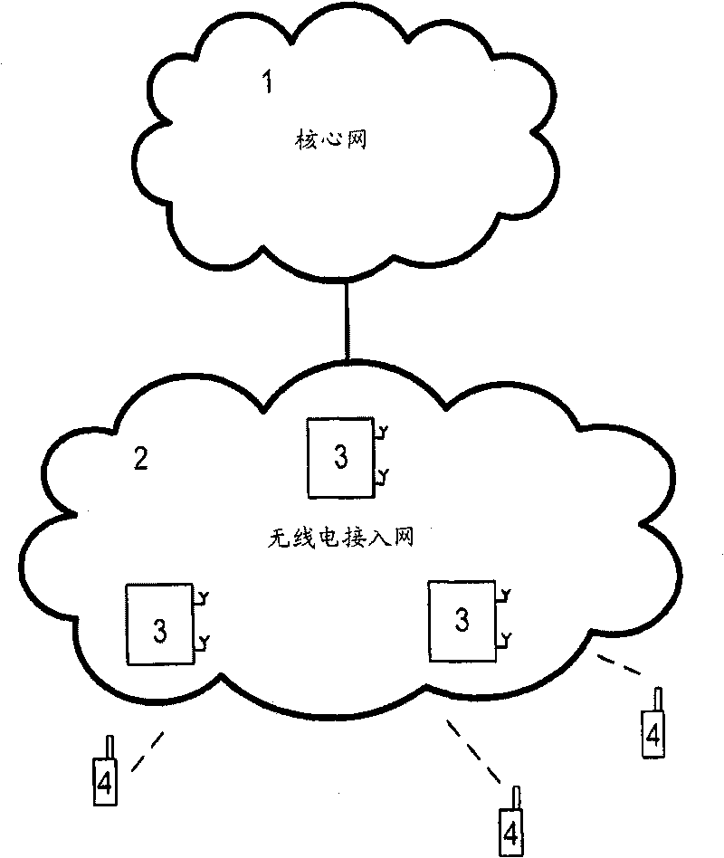
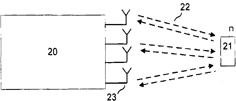
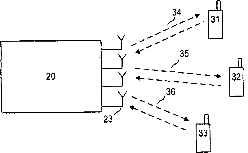
[0022] The present invention involves such as figure 1 The cellular telecommunications system shown. The present invention proposes a method and device for multi-user MIMO signal transmission in a telecommunication system. The basic idea of ​​the invention is to exploit the fact that MU-MIMO and SU-MIMO share many similarities. But they are currently divided into two very different modalities, but there is much to be gained by exploiting commonality between the two modalities to reduce the number of signaling options. This will not only mean simpler implementation of transmitters and receivers, but also ease of testing equipment to ensure it meets standards.

[0023]When transmitting in SU-MIMO mode or MU-MIMO mode, the precoding matrix needs to be selected by the base station for transmission. ...


PUM


Abstract

The present invention relates to a method and arrangements in a communication system for Multi User Multiple-Input-Multiple-Output (MU-MIMO) signaling via Multiple-Input-Multiple-Output (MIMO) antennas between a base station and one of a plurality of mobile terminals supporting both Single User and Multi User Multiple- Input-Multiple-Output (SU-MIMO and MU-MIMO) signaling modes. Switching between the modes is supported in the system and the modes have partly shared signaling. SU-MIMO mode signaling which is redundant, i.e. not needed, for MU- MIMO mode signaling is identified. Bits, i.e. data bits, of the identified redundant signaling is re-interpreted or re-defined to comprise signaling information associated with MU-MIMO mode. The signaling information associated with MU-MIMO mode is signaled to the mobile terminal by using the reinterpreted redundant bits.

Description

technical field [0001] The present invention relates to methods and arrangements in telecommunication systems. In particular, it relates to methods and devices for multi-user MIMO signaling in telecommunication systems. Background technique [0002] Usually includes (such as figure 1 In the shown) cellular telecommunication system of core network 1, radio access network 2, user equipment (UE) 4 and base station 3, multiple transmit antennas can be used in various ways to achieve high data rates. If the receiver also has multiple antennas, a Multiple Input Multiple Output (MIMO) channel is formed. One application in this type of setup is the pursuit of high peak rates for individual users. By transmitting over several layers (which means that the information is transmitted over several bit streams), the information is spread in the spatial domain, a substantial improvement in data rate can be achieved under good channel conditions. This is called Single User MIMO (SU-MIMO...

Claims


Application Information

Patent Timeline
Patent Type & Authority Applications(China)
IPC IPC(8): H04B7/06
CPCH04B7/0689H04B7/12H04W52/54H04B7/0452H04B7/0469H04W72/23H04B7/0486H04L5/0048H04W52/36H04W88/06H04W88/10
Inventor G·琼格伦B·戈兰森万蕾
Owner UNWIRED PLANET
Learn More