
Motorbike

A technology for motorcycles and vehicles, applied in vehicle parts, bicycle accessories, optical signals, etc., and can solve problems such as low intensity

Active Publication Date: 2010-06-23
YAMAHA MOTOR CO LTD
View PDF0 Cites 3 Cited by
  • Summary
  • Abstract
  • Description
  • Claims
  • Application Information

AI Technical Summary

Problems solved by technology

This is due to the fact that usually the side cover is larger than the license plate holder and therefore less strong than the license plate holder

Method used


Image

  • Motorbike
  • Motorbike
  • Motorbike

Examples


Embodiment Construction

[0028]

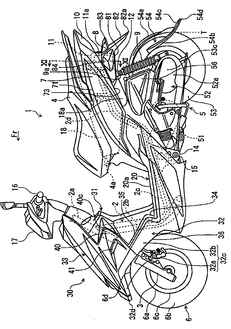
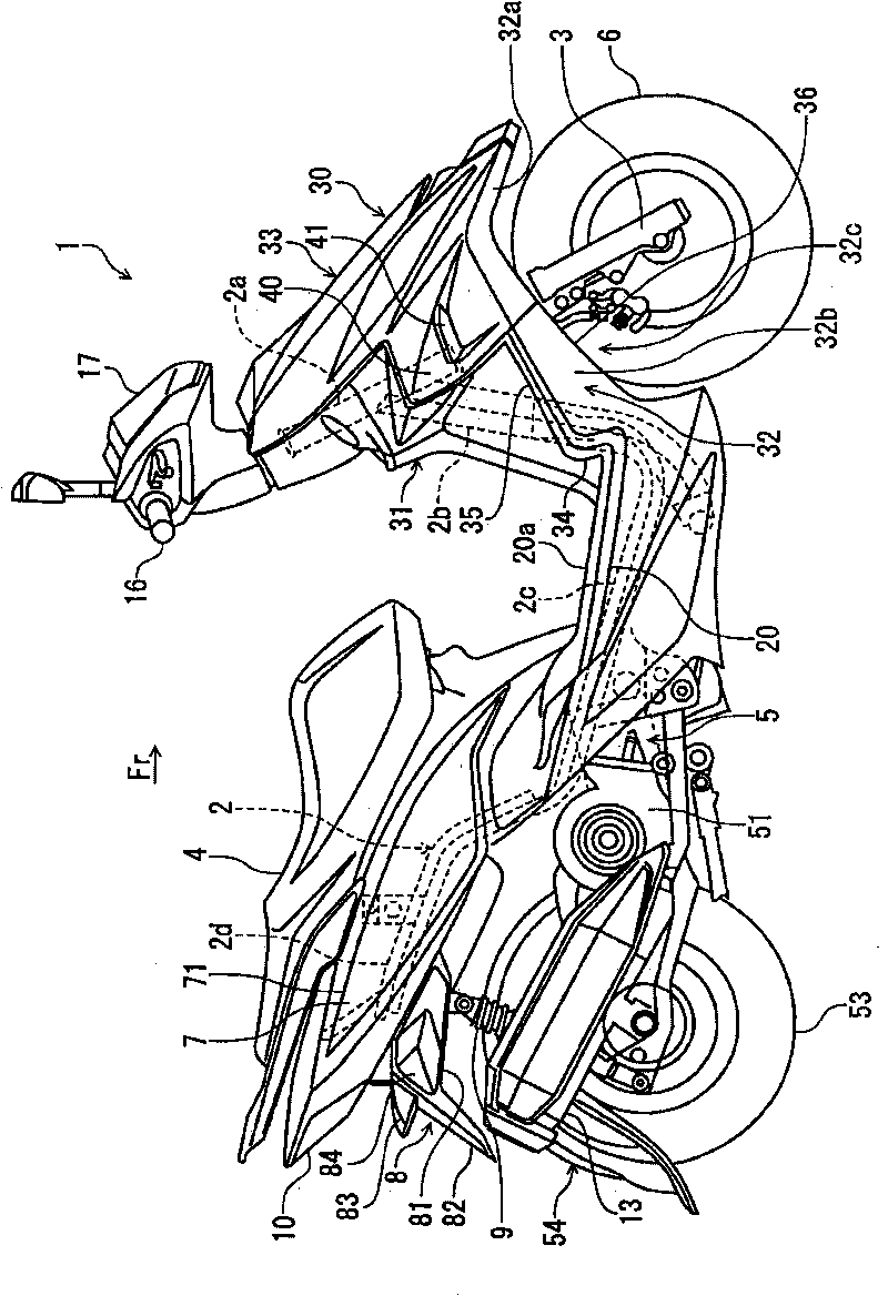
[0029] like figure 1 As shown, the motorcycle of this embodiment is a scooter 1 . However, the motorcycle of the present invention is not limited to the scooter 1, and may be other motorcycles. In the following description, the front, rear, left, and right directions represent the front, rear, left, and right directions as viewed from the rider riding on the scooter 1, respectively. figure 1 The symbol Fr in represents the front.

[0030] The scooter 1 has a frame 2 . The frame 2 includes: a head pipe 2a, a lower frame 2b extending obliquely downward from the head pipe 2a backward, a lower frame 2c extending rearward from the lower portion of the lower frame 2b, and a lower frame 2c extending backward from the rear portion of the lower frame 2c. Seat beam 2d extending obliquely upward.

[0031] A bracket 14 protruding downward is provided on the lower frame 2c. The engine unit 5 is attached to the bracket 14 via a pivot 15 . Accordingly, the front end of the...


PUM


Abstract

The present invention discloses a motorbike capable of guaranteeing the support strength and the visibility of the rear turn signal light thereof and preventing the protrusion of the rear turn signal light from the motorbike body. The pedestal motorbike (1) comprises a license plate rack (8), so that the pedestal motorbike is supported by a frame (2) at a position lower than a tail light (10), wherein the license plate rack (8) comprises a rear portion (82) for supporting a license plate and a side portion (81) which extends forwards from the rear portion (82) along the lower edge (73) of a side cover (7) and is provided with a rear turn signal light t (84); when viewed vertically, the rear turn signal light (84) is arranged at a position superposed with a protrusion portion (71) in such a manner that part of the rear turn signal light (84) is hidden by the protrusion portion (71) of the side cover (7); and when viewed laterally, the rear end of the rear turn signal light t (84) is disposed on the front portion of the outline of the rear side of the motorbike body formed by the license plate rack (8) and the tail light (10).

Description

technical field [0001] The present invention relates to motorcycles. Background technique [0002] Among conventional motorcycles, there is known a motorcycle provided with a license plate holder at the rear of the vehicle body. Disclosed in the following patent document 1 as Figure 18 The illustrated license plate frame 101 extends rearward and obliquely downward from the rear of the vehicle body. The license plate holder 101 includes a rear portion 103 disposed below the tail lamp 102 and extending downward, and a rear turn signal support portion 104 protruding left and right from the left and right sides of the rear portion 103 . The rear blinker support portion 104 supports left and right rear blinkers 105 formed separately from the tail lights 102 . [0003] According to such a configuration, since the distance between the tail lamp 102 and the left and right rear turn lamps 105 can be sufficiently ensured, it is easy to clearly distinguish the lighting conditions of...

Claims


Application Information

Patent Timeline
Patent Type & Authority Applications(China)
IPC IPC(8): B60R13/10B62J6/04
Inventor 廖崇本
Owner YAMAHA MOTOR CO LTD
Learn More