Work vehicle

a technology for working vehicles and fuel tanks, applied in the direction of machines/engines, liquid fuel feeders, electric propulsion mountings, etc., can solve the problems of limiting the expansion of the fuel tank to an entire capacity, the weight of the tank support plate is reduced, and the battery is strengthened. the effect of strength

Active Publication Date: 2017-08-10
YANMAR POWER TECHNOLOGY CO LTD
View PDF0 Cites 3 Cited by
  • Summary
  • Abstract
  • Description
  • Claims
  • Application Information

AI Technical Summary

Benefits of technology

[0018]With the embodiment of the invention of the present application, the tank support plate is configured to include the front and rear transverse frames supported by the rear frame, and only the fuel tank mounting part is configured by the plate. This ensures support strength to support the fuel tanks that become heavy, while reducing the weight of the tank support plate. Further, by fastening the front and rear transverse frames to the beam frame and the transmission section, the tank support plate to support the fuel tank that becomes heavy is secured to the highly rigid beam frame and the transmission section, thereby making it possible to support the fuel tanks in a highly rigid and stable manner.
[0019]With the embodiment of the invention of the present application, the battery is supported by the body frame that is a strength member with the bracket interposed therebetween, thus leading to improved strength to support the battery. Additionally, the battery can be disposed at a position close to each of the engine and the operator's seat which are located outside the hood and need power supply. This contributes to reduction of a power supply harness.
[0020]With the embodiment of the invention of the present application, the step is supported by the body frame that is a strength member with the bracket and the front transverse frame interposed therebetween. This makes it possible to improve the strength to support the step. Furthermore, with the invention of the present application, draining in a direction free from covering by the wind direction plate is attainable by covering the drain hole with the wind direction plate. This prevents failures due to heat damage or water leak in components having low heat resistance or water resistance, such as the harness and the battery disposed adjacent to the exhaust pipe, when water that becomes hot in the exhaust pipe is drained to the outside.

Problems solved by technology

However, in the mounting space of the work vehicle, not only the diesel engine itself but also the exhaust-gas purification device becomes extremely hot due to heat generation from the diesel engine being driven.
An installation position of the fuel tank is also limited, and hence there is a limit in increasing an entire capacity of the fuel tank, and it is also obstructive to getting on and off of the operator depending on the shape of the fuel tank.

Method used


Image

  • Work vehicle
  • Work vehicle
  • Work vehicle

Examples


Embodiment Construction

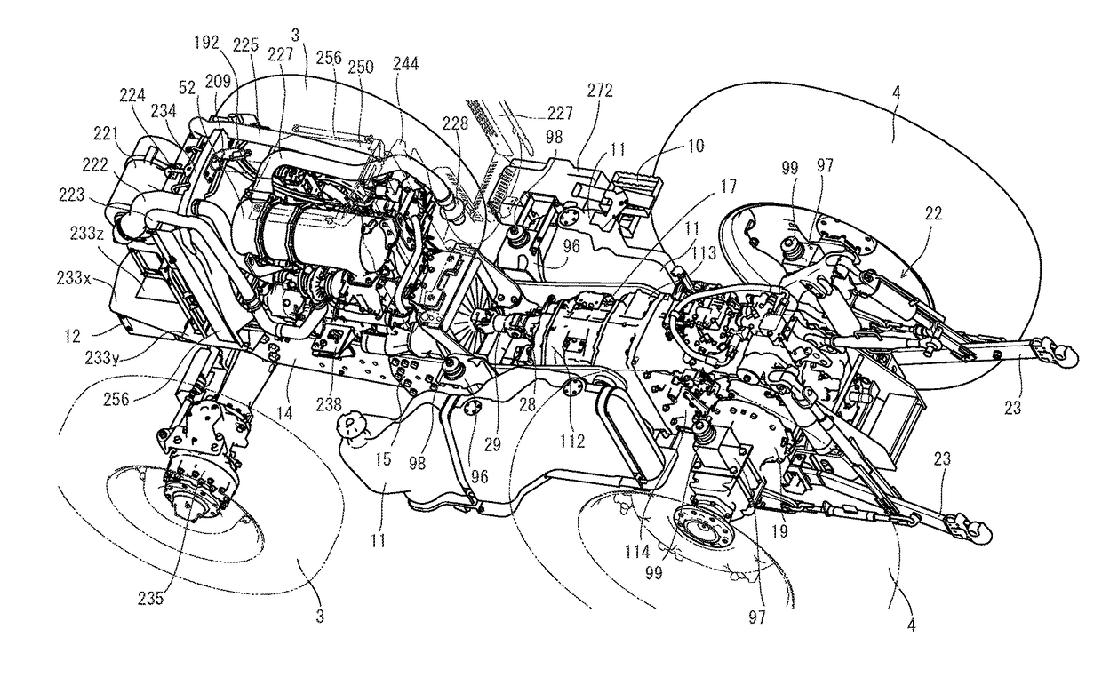
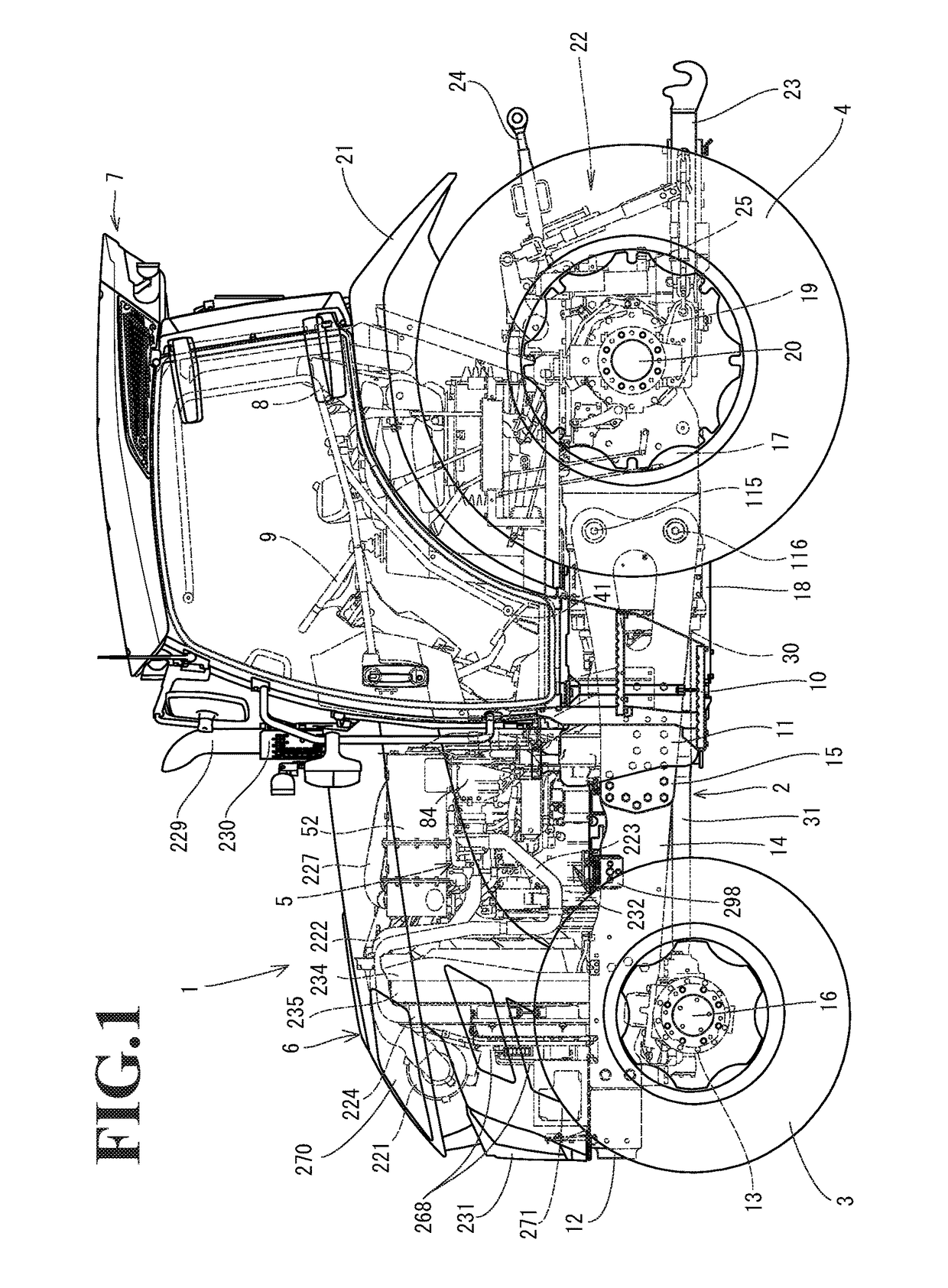
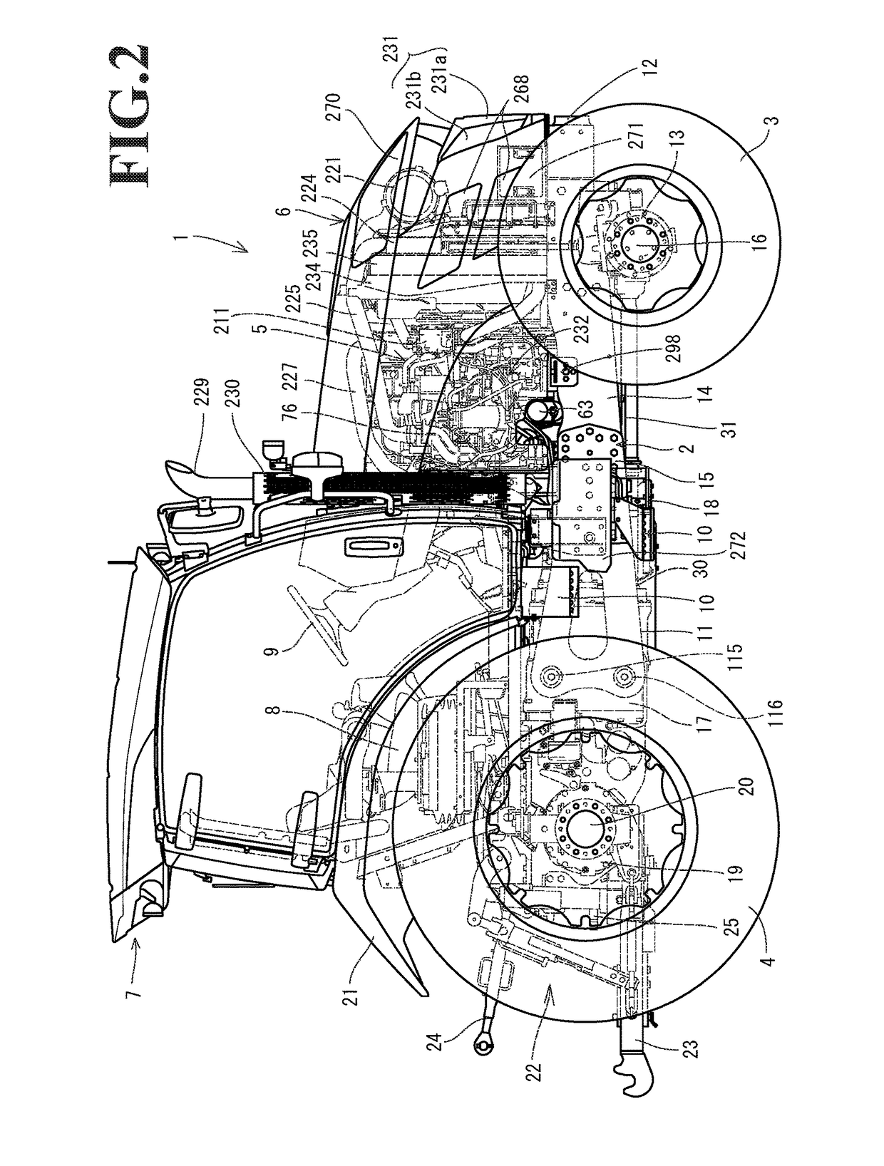
[0054]Hereinafter, an embodiment of the present invention will be described with reference to the drawings. First, a configuration of a tractor 1 according to the embodiment will be described with reference to FIGS. 1 to 10. The tractor 1 is a work vehicle. The tractor 1 of this embodiment includes a travelling machine body 2. The travelling machine body 2 is supported by travelling sections. The travelling sections are a pair of left and right front wheels 3 and a pair of left and right rear wheels 4 in this embodiment. The rear wheels 4 and the front wheels 3 are driven by a power source mounted on the front section of the travelling machine body 2. The power source is a common rail diesel engine 5 (hereinafter, simply referred to as the engine) in this embodiment. The tractor 1 travels forward and backward by driving the rear wheels 4 and the front wheels 3. The engine 5 is covered with a hood 6. A cabin 7 is provided on the upper surface of the travelling machine body 2. An oper...


PUM


Abstract

In the work vehicle, a pair of left and right fuel tanks is distributed into left and right sides of a traveling body. A tank support plate to support the fuel tanks from below is made up of a pair of front and rear transverse frames extended leftward and rightward below the left and right rear frames, and a pair of left and right tank mounting plates on which the front and rear transverse frames are held in a back-and-forth direction on both left and right sides. The left and right fuel tanks are respectively mounted and secured onto the left and right tank mounting plates. A support mount and the front transverse frame are coupled to each other by a coupling bracket.

Description

CROSS-REFERENCE TO RELATED APPLICATIONS[0001]The present application is a continuation application of International Application No. PCT / JP2015 / 078381, filed Oct. 6, 2015, which claims priority to Japanese Patent Application No. 2014-211347, filed Oct. 16, 2014. The contents of these applications are incorporated herein by reference in their entirety.BACKGROUND OF THE INVENTION[0002]The invention of the present application relates to work vehicles.[0003]As higher-level emission regulations have been applied to diesel engines, agricultural machines, construction machines, and ships that include a diesel engine are required to include a post-processing device, such as an exhaust-gas purification device that removes air pollutants in exhaust gas. Therefore, when mounting an exhaust-gas purification device, in some of work vehicles of related art, such as tractors, the exhaust gas purification device is disposed together with a diesel engine inside an engine compartment below a hood (ref...

Claims


Application Information

Patent Timeline
Patent Type & Authority Applications(United States)
IPC IPC(8): B60K15/067F02M37/22B60K1/04F02M37/26
CPCB60K15/067B60Y2200/221F02M37/22B60K1/04F02M37/00B60K2015/03118B60K15/063F02M37/26F02M37/24B60R3/02B60K2015/03453B60Y2200/415
Inventor KOMIYA, TOSHITAKA
Owner YANMAR POWER TECHNOLOGY CO LTD
Why Eureka
Try Eureka