
Engine device

a technology of engine and support body, which is applied in the direction of combustion engines, engine cooling apparatus, casings, etc., can solve the problems of inability to compactly form the piping structure of the intake pipe, the inability to easily install the engine, and the inability to ensure the support strength of the intake pipe support body, so as to achieve the support structure of the lower side exhaust pipe, the effect of easy simplified support structure and high rigidity

Active Publication Date: 2019-03-12
YANMAR POWER TECHNOLOGY CO LTD
View PDF19 Cites 0 Cited by
  • Summary
  • Abstract
  • Description
  • Claims
  • Application Information

AI Technical Summary

Benefits of technology

The invention describes an engine device with two superchargers arranged in series. The first supercharger and second supercharger are positioned on the sides of the engine cylinder blocks. The exhaust pipes and intake pipe are designed to be flush with the engine's head cover, making the installation process compact. The engine device also includes an exhaust inlet connected to the cylinder head, an upper side exhaust pipe connected to the lower side exhaust pipe via a bracket body, and a fixedly set upper side and lower side exhaust pipes at the same height. The intake pipe is attached to the head fixing bolt, ensuring strong support. Additionally, attachment components like an oil cooler and engine operating tool can be positioned on either side of the engine, improving operational workspace and preventing exhaust heat from affecting the operator.

Problems solved by technology

As in Patent document 1, in a structure in which a high pressure supercharger, an aftercooler, or the like, is installed on an upper face of an engine, an installation height dimension of the engine is large, causing a problem such as inability to easily install the engine in a vessel or the like, in which the installation height dimension of the engine is limited.
Thus, each exhaust pipe or the intake pipe is likely to protrude from the side face portion of the one side of the engine block toward its outward side, causing a problem such as inability to compactly form a piping structure of the exhaust pipe, the intake pipe, or the like.
This results in a problem such as easy movement of an operator.

Method used


Image

  • Engine device
  • Engine device
  • Engine device

Examples


Embodiment Construction

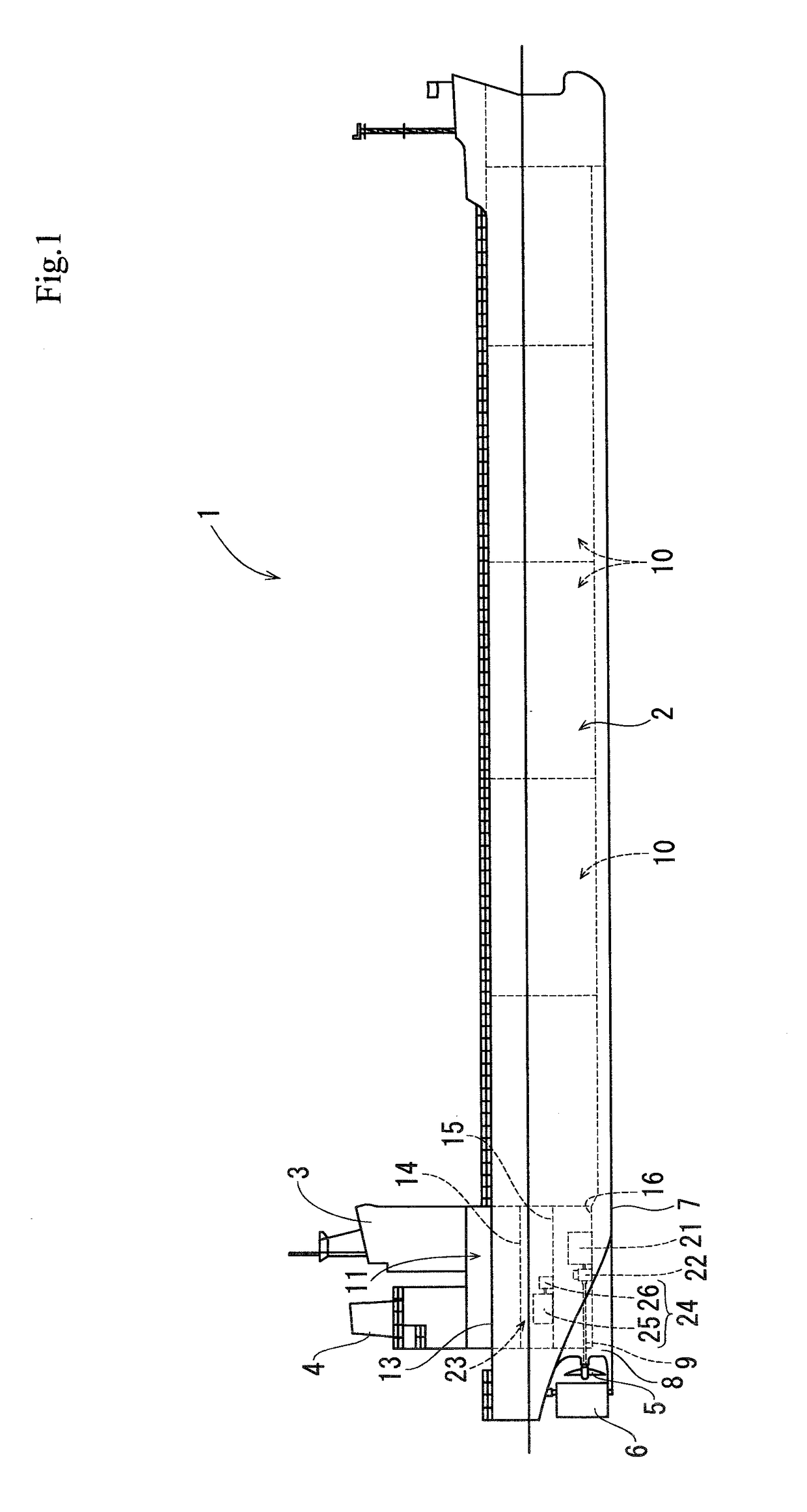
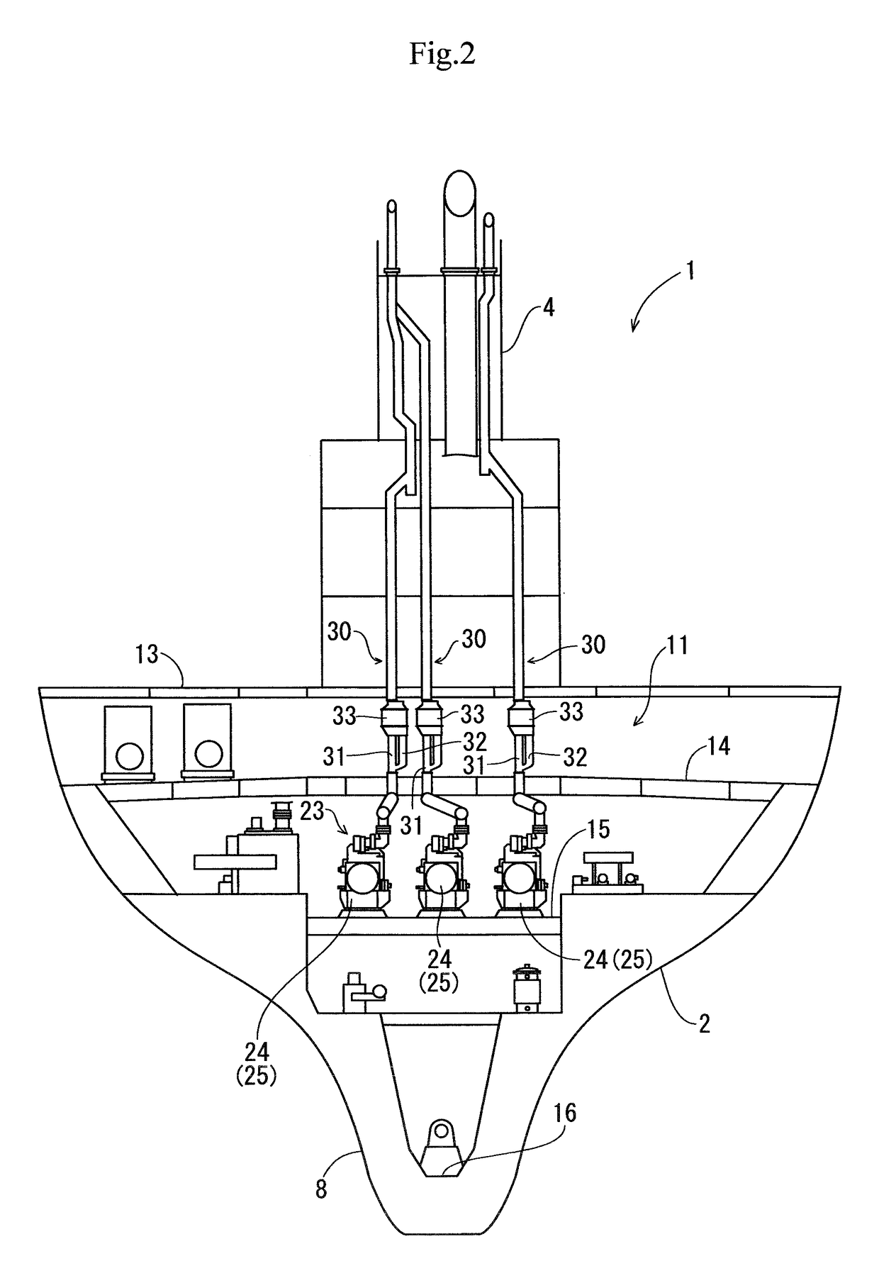
[0032]An embodiment in which the invention of the present application has been embodied will be described below on the basis of drawings of a case in which the invention is applied to a diesel engine of a power generator installed in a vessel.

[0033]First, an outline of a vessel 1 in which a diesel engine is installed will be described with reference to FIGS. 1 and 2. As illustrated in FIGS. 1 and 2, the vessel 1 includes a vessel body 2, a cabin 3 (bridge) provided on a stern of the vessel body 2, a funnel 4 disposed behind the cabin 3, and a propeller 5 for propulsion and a rudder 6 for steering that are provided at a rear lower portion of the vessel body 2. In addition, a stern skeg 8 is integrally formed on a vessel bottom 7 at the rear lower portion of the vessel body 2, and a propelling shaft 9 that rotationally drives the propeller 5 for propulsion is included and supported by the stern skeg 8. Holds 10 are provided at a stem side and a central portion in the vessel body 2. An...


PUM


Abstract

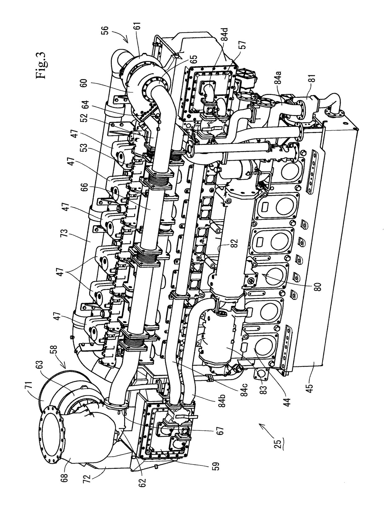
An engine device in which exhaust pipes and an intake pipe can be mounted highly rigidly by using an upper face corner of a cylinder block in an engine, and a support structure of the exhaust pipes and the intake pipe can be simplified. In an engine device in which a first supercharger and a second supercharger are disposed in series on an exhaust gas discharge path of an engine, the engine device has a structure in which the first supercharger and the second supercharger are disposed to be divided on opposed side faces of the engine, and an upper side exhaust pipe between the engine and the first supercharger, a lower side exhaust pipe between the first supercharger and the second supercharger, and an intake pipe between the first supercharger and the second supercharger extend to be substantially flush with one another at a head-cover disposed-height of an upper face of the engine.

Description

TECHNICAL FIELD[0001]The invention of the present application relates to engine devices to be installed in vessels, etc., and relates to an engine device including a two-stage supercharger that efficiently burns fuel.BACKGROUND OF THE INVENTION[0002]Hitherto, referring to, for example, prior art documents, there is a technique (see, for example, Patent Document 1, Patent Document 2, etc.) in which, in an engine provided with a high pressure supercharger and a low pressure supercharger, by increasing a supply air pressure of the engine, an increase in combustion efficiency is achieved while preventing a supply air temperature of the engine from increasing.PATENT DOCUMENTS[0003]Patent document 1: Japanese Unexamined Patent Application Publication No. 06-66146[0004]Patent document 2: International Publication No. 2012 / 016712SUMMARY OF INVENTION[0005]As in Patent document 1, in a structure in which a high pressure supercharger, an aftercooler, or the like, is installed on an upper face ...

Claims


Application Information

Patent Timeline
Patent Type & Authority Patents(United States)
IPC IPC(8): F02B37/013F01P11/08F02B37/02F02B37/00F02F7/00F02B61/04
CPCF02B37/013F01P11/08F02B37/004F02B61/04F02F7/006F02B37/025Y02T10/144F02F2007/0063Y02T10/12
Inventor NAKAGAWA, TOSHIAKINODA, TAKEHIROHANADA, YUUYAHAMAOKA, SHUNJI
Owner YANMAR POWER TECHNOLOGY CO LTD
Learn More