Vehicle lower body structure

A technology for the rear of the vehicle and the vehicle, which is applied in the directions of vehicle components, superstructure, and sub-assembly of the superstructure, can solve the problems of increasing the beam and the weight of the body, and achieve the effect of increasing the strength

Inactive Publication Date: 2012-10-24
TOYOTA JIDOSHA KK
View PDF1 Cites 0 Cited by
  • Summary
  • Abstract
  • Description
  • Claims
  • Application Information

AI Technical Summary

Problems solved by technology

However, increasing the size of the beam (14A, 16) or increasing the thickness of the beam (14A, 16) increases the weight of the vehicle body

Method used


Image

  • Vehicle lower body structure
  • Vehicle lower body structure
  • Vehicle lower body structure

Examples


Embodiment Construction

[0021] Next, a vehicle lower body structure according to an exemplary embodiment of the present invention will be described with reference to the drawings. In the drawings, the same reference numerals denote the same or corresponding parts. In addition, the same or corresponding parts are described only once below.

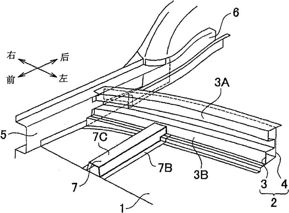
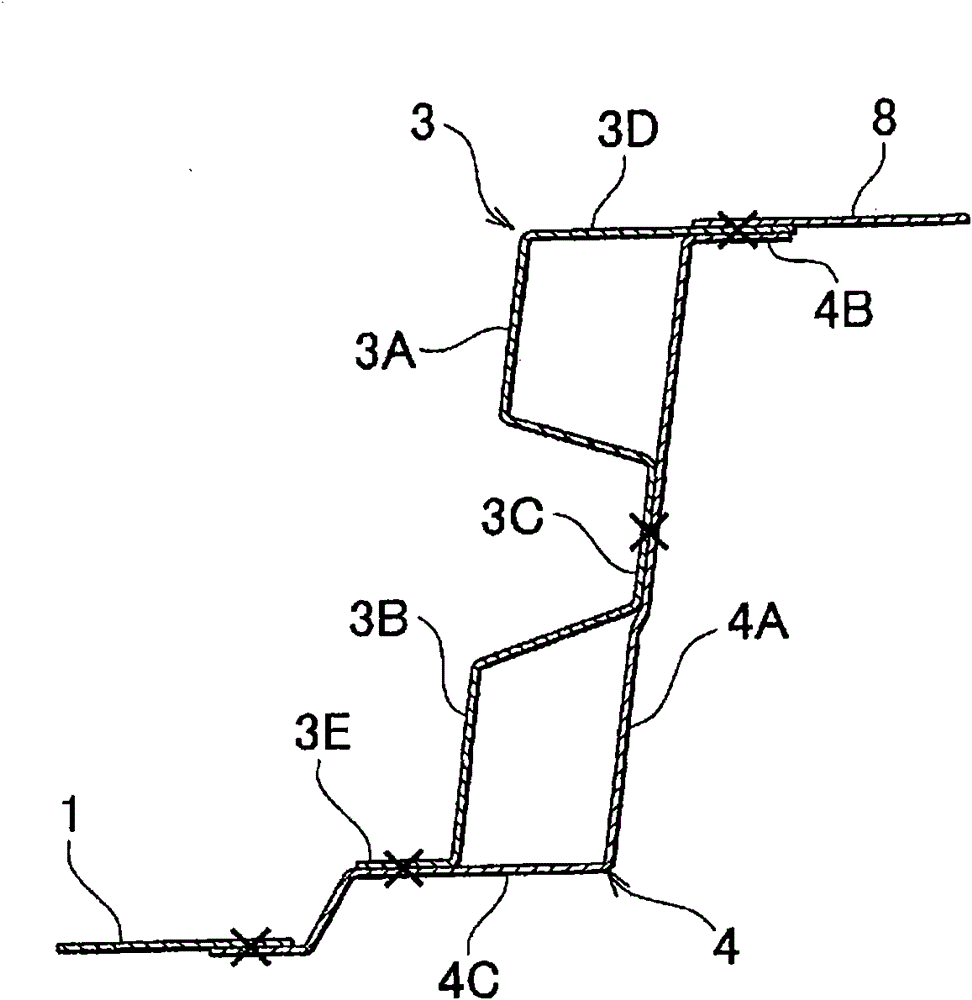
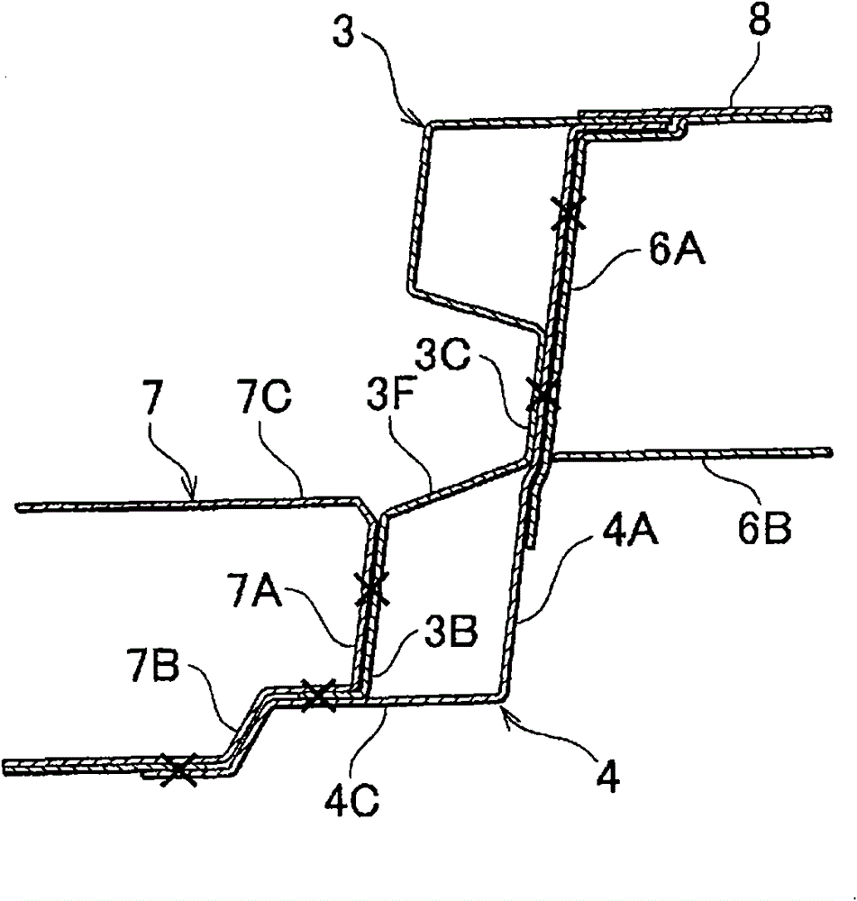
[0022] The vehicle lower body structure according to the first embodiment of the present invention is, for example, the structure of the lower portion of a vehicle compartment of an automobile. Such as figure 1 As shown in , at the rear of a front floor (floor panel) 1 forming a lower portion of the vehicle compartment, a center floor beam 2 is arranged as a beam forming a step extending upward from the front floor 1 . The central floor cross member 2 is formed by a front cross member 3 as a first cross member delimiting a part of the vehicle body and facing the front of the vehicle body, and a rear cross member 4 as a second cross member connected to the front...


PUM


Abstract

A vehicle lower body structure includes a cross member 2 that extends in the vehicle-width direction, that defines part of a vehicle compartment, and that includes a first cross member 3, 13, 23 which is formed of a plate member and a second cross member 4, 14, 24 which is formed of a plate member and which is arranged at a position closer to the rear of a vehicle than the first cross member 3, 13, 23, the first cross member 3, 13, 23 and the second cross member,4, 14, 24 facing each other. A plurality of closed section portions is formed by the first cross member 3, 13, 23 and the second cross member 4, 14, 24. The closed section portions are connected to each other via a portion at which the first cross member and the second cross member are continuously overlapped with each other.

Description

technical field [0001] The present invention relates to a vehicle body structure such as an automobile, and more particularly to a vehicle lower body structure including a cross member extending in a vehicle width direction. Background technique [0002] There is a vehicle underbody structure of an automobile in which a step portion, a so-called raised portion (raised portion) is formed on the floor of the vehicle compartment. Japanese Patent Application Publication No. 2006-290140 (JP-A-2006-290140) (particularly reference abstract and image 3 ) describes a vehicle underbody structure of this type. According to JP-A-2006-290140, the second raised portion (5) is formed on the floor panel (2) at the middle portion in the front-rear direction, and the second raised portion (5) is provided with beams (14A, 16 ) extending in the vehicle width direction and forming a closed section portion (15A, 17). [0003] In the vehicle lower body structure described in JP-A-2006-290140, t...

Claims


Application Information

Patent Timeline
Patent Type & Authority Patents(China)
IPC IPC(8): B62D25/20
CPCB62D25/025B62D25/20B62D25/2027B62D25/2036
Inventor 森健雄
Owner TOYOTA JIDOSHA KK
Why Eureka
Try Eureka