Load Bearing Frame

a technology of load bearings and frame frames, which is applied in the direction of buildings, towers, walls, etc., can solve the problems of small deformation of the entire frame and sudden collapse of the entire frame, and achieve the effect of improving the load bearing capacity of the entire fram

Inactive Publication Date: 2010-02-11
KOBE STEEL LTD
View PDF8 Cites 8 Cited by
  • Summary
  • Abstract
  • Description
  • Claims
  • Application Information

AI Technical Summary

Benefits of technology

[0013]According to the above configuration, even in the case where force in the direction of leaving apart from the pillar materials is imposed on the diagonal materials, energy is absorbed by plastic deformation of the connection members. Therefore, the load bearing capacity of the entire frame is improved.

Problems solved by technology

In the load bearing frame of the above structure, force is smoothly transmitted, while in the case where an excessive horizontal load is imposed, there is a problem that a stress is concentrated on the diagonal materials and connection parts so that buckling of the diagonal materials and breakage of the connection parts are generated in an earlier stage and thus deformability of the entire frame is small.
Therefore, there is sometimes a case where after a maximum load is obtained, the entire frame suddenly collapses.

Method used


Image

  • Load Bearing Frame
  • Load Bearing Frame
  • Load Bearing Frame

Examples


Embodiment Construction

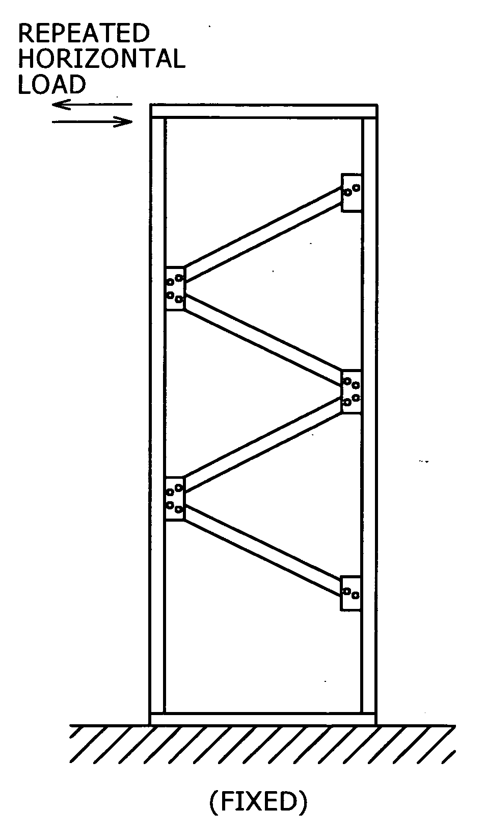
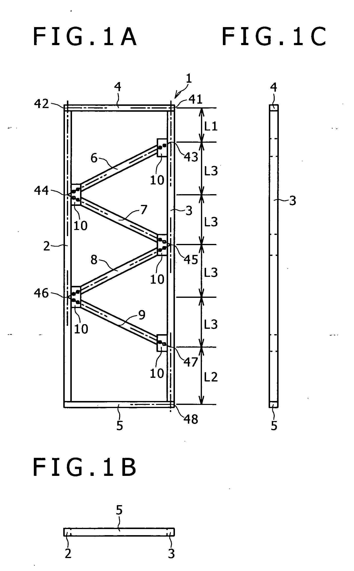
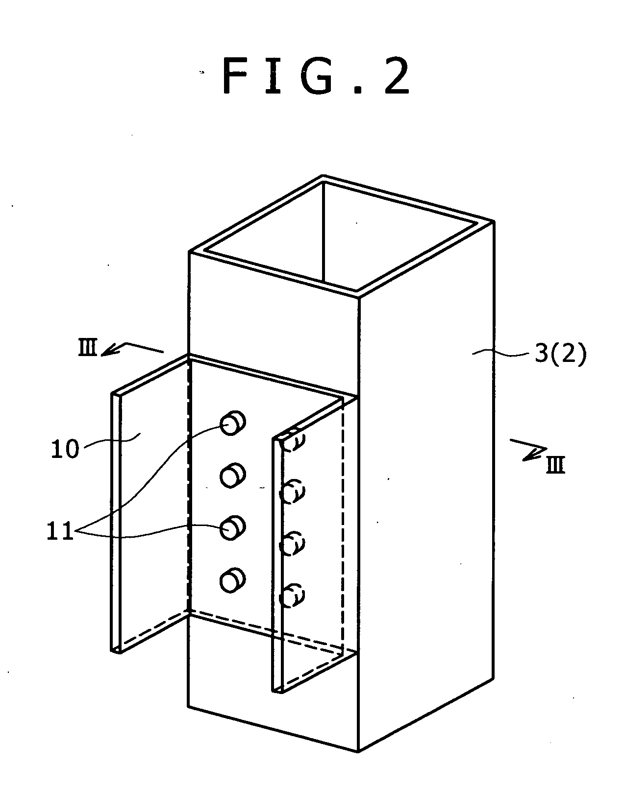
[0028]Hereinafter, a description will be given to preferred embodiments of the present invention with reference to drawings. FIG. 1 is a view showing a schematic configuration of a load bearing frame according to a first embodiment of the present invention. FIG. 1A is a front view, FIG. 1B is a bottom view and FIG. 1C is a side view. FIG. 2 is an enlarged view of the vicinity of a connection part between a pillar material and a connection member. Although FIG. 2 shows the vicinity of a connection part between a pillar material 3 and a connection member 10, a configuration of the vicinity of a connection part between a pillar material 2 and the connection member 10 is the same. FIG. 3 is a sectional view by line III-III of FIG. 2.

[0029]A load bearing frame 1 (hereinafter, referred to as the frame 1) shown in FIG. 1 is a steel frame for a steel house. The frame 1 has two pillar materials 2 and 3, two frame materials 4 and 5 and four diagonal materials 6 to 9. The pillar materials 2 an...


PUM


Abstract

The present invention is to provide a load bearing frame for suppressing generation of buckling of diagonal materials and breakage of connection parts and having high deformability.
A load bearing frame 1 has two pillar materials 2 and 3, two frame materials 4 and 5 and four diagonal materials 6 to 9. A connection point 41 between the pillar material 3 and the frame material 4 is apart from a connection point 43 between the diagonal material 6 arranged on the uppermost side and the pillar material 3 by a distance L1. A connection point 48 between the pillar material 3 and the frame material 5 is apart from a connection point 47 between the diagonal material 9 arranged on the lowermost side and the pillar material 3 by a distance L2.

Description

TECHNICAL FIELD[0001]The present invention relates to a load bearing frame used for forming a wall surface of a building.BACKGROUND ART[0002]A general load bearing frame is formed in a truss structure of a substantially rectangular shape in which both ends of two pillar materials are respectively connected by two frame materials, and the two pillar materials are diagonally connected by a plurality of diagonal materials (refer to Patent Documents 1 and 2 for example). Here, in the conventional load bearing frame, connection points between diagonal materials arranged on the uppermost side and the lowermost side and pillar materials correspond to corner parts of a frame. In the load bearing frame of the above structure, force is smoothly transmitted, while in the case where an excessive horizontal load is imposed, there is a problem that a stress is concentrated on the diagonal materials and connection parts so that buckling of the diagonal materials and breakage of the connection part...

Claims


Application Information

Patent Timeline
Patent Type & Authority Applications(United States)
IPC IPC(8): E04H12/04
CPCE04B1/24E04B2001/2496E04B2001/2454E04B2001/2415E04B2/56E04C2/38
Inventor NAKAGAWA, TOMOKAZUHATANAKA, TADAOKARATSU, TOSHIKAZUHIURA, NOBUOTAMADA, TETSUOMORII, TAKESHISUGA, TAKEOWATANABE, FUMIO
Owner KOBE STEEL LTD
Why Eureka
Try Eureka