Camshaft bearing structure for engine

A camshaft and engine technology, applied in the direction of engine components, machines/engines, mechanical equipment, etc., can solve problems such as unfavorable engine weight reduction and engine compactness

Active Publication Date: 2010-06-23
CHERY AUTOMOBILE CO LTD
View PDF0 Cites 14 Cited by
  • Summary
  • Abstract
  • Description
  • Claims
  • Application Information

AI Technical Summary

Problems solved by technology

This structure lengthens the cylinder head as a whole because the first gear camshaft cover needs to be arranged at the front end, especially for VVT engines that are widely used at present. Th

Method used


Image

  • Camshaft bearing structure for engine
  • Camshaft bearing structure for engine
  • Camshaft bearing structure for engine

Examples


Embodiment Construction

[0028] The present invention will be specifically described below in conjunction with the accompanying drawings.

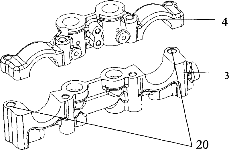
[0029] Such as Figure 5 , 6 As shown, the camshaft bearing assembly consists of a single first camshaft bearing and several identical second camshaft bearings. The lower half bearing of the second camshaft bearing is integrated on the cylinder head 1, and the upper bearing cover 2 of a separate or integral frame type is used. The independent first camshaft bearing is divided into upper and lower bearing caps 4 and 3, and the front end of the cylinder head is provided with a mounting boss. The upper and lower covers of the first camshaft bearing are positioned by two sets of positioning sleeves 5, and the fastening bolts 6 pass through the positioning sleeves. 5. Fasten the upper and lower bearing caps on the cylinder head.

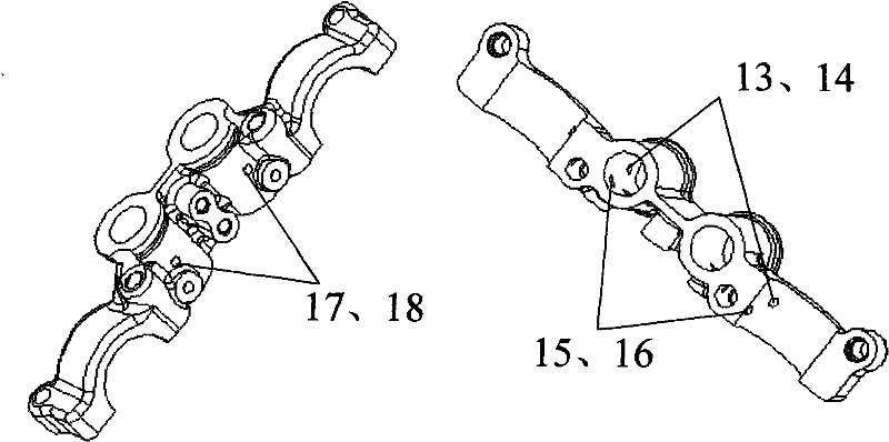
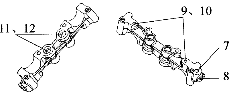
[0030] Such as Figure 2-4 As shown, there are oil passages arranged in the upper and lower covers of the first camshaft bearing, which ...


PUM


Abstract

The invention discloses a camshaft bearing structure for an engine, which consists of a first camshaft bearing and a plurality of same second camshaft bearings. The camshaft bearing structure for the engine is characterized in that: lower-half bearings of the second camshaft bearings are integrated on a cylinder cover; the first camshaft bearing is independent and not integrated on the cylinder cover. The first camshaft bearing is divided into an upper bearing cover and a lower bearing cover, is positioned by a positioning sleeve and is fixed on the cylinder cover through a fastening bolt. Oil ways are distributed in the upper cover and the lower cover of the first camshaft bearing and are used for introducing the pressure oil from the cylinder and providing oil for a hydraulic tappet, camshaft lubrication and a VVT phaser. By the independence of the first camshaft bearing, the front-end size of the cylinder cover can be obviously reduced, and the compactness of the engine can be improved. Meanwhile, the oil ways are arranged in the camshaft bearing covers, so that the camshaft bearing structure for the engine has the function of building a lubricating oil way, thereby simplifying the arrangement of the lubricating oil way of the cylinder cover.

Description

technical field [0001] The invention relates to a new type of engine camshaft bearing combination and arrangement structure. Background technique [0002] The gasoline engine of existing overhead camshaft structure mostly makes all camshaft lower bearings on the cylinder head, and the camshaft upper bearing cap is made into a separate or integral (frame type) form. This structure lengthens the cylinder head as a whole because the first gear camshaft cover needs to be arranged at the front end, especially for VVT engines that are widely used at present. There are multiple oil passages arranged on the first bearing, which makes the lengthening of the cylinder head more obvious. It is beneficial to reduce the weight of the engine and improve the compactness of the engine. Contents of the invention [0003] The purpose of the present invention is to provide a new type of camshaft bearing structure, by separating the first gear bearing of the camshaft from the cylinder head, a...

Claims


Application Information

Patent Timeline
IPC IPC(8): F01L1/047F01M9/10
CPCF01L2001/0476
Inventor 谢小祥刘文军
Owner CHERY AUTOMOBILE CO LTD
Why Eureka
Try Eureka