Camera lens

A camera lens and lens technology, applied in the field of camera lenses, can solve the problems of bulky, bulky, inconvenient operation and carrying of smartphones, and achieve the effects of avoiding process processing, good image quality, and reducing the size of the front end of the lens

Pending Publication Date: 2019-02-19
ZHEJIANG SUNNY OPTICAL CO LTD
View PDF0 Cites 4 Cited by
  • Summary
  • Abstract
  • Description
  • Claims
  • Application Information

AI Technical Summary

Problems solved by technology

However, although the camera lens of the existing smart phone has a large field of view, its volume is relatively large, which makes the thickness or volume of the smart phone larger after being loaded into the smart phone, and the smart phone becomes bulky, making the operation and portability difficult. more inconvenient

Method used


Image

  • Camera lens
  • Camera lens
  • Camera lens

Examples


Embodiment approach 1

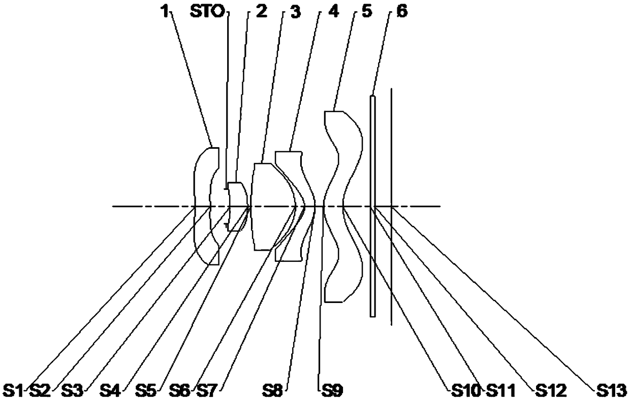
[0074] figure 1 A structural layout diagram of the imaging lens according to Embodiment 1 of the present invention is schematically shown.

[0075] The following table 3 lists the relevant parameters of each lens of this embodiment, including surface type, radius of curvature, thickness, material refractive index and Abbe number and conic coefficient:

[0076]

[0077]

[0078] table 3

[0079] In this embodiment, the data of each lens surface is shown in Table 4 below:

[0080] surface

A4

A6

A8

A10

A12

A14

A16

A18

A20

S1

1.9565E-01

-1.6660E-01

1.5875E-01

-1.0647E-01

4.8292E-02

-1.2398E-02

1.4269E-03

0.0000E+00

0.0000E+00

S2

5.6209E-01

-1.2231E+00

3.4011E+00

-6.7084E+00

8.4874E+00

-5.8076E+00

1.5873E+00

0.0000E+00

0.0000E+00

S3

-1.9438E-01

8.3804E-01

-1.7018E+01

1.7477E+02

-9.4173E+02

2.6020E+03

-3.0299E+03

0.0000E+00

0.0000E+00

S...

Embodiment approach 2

[0085] Figure 6 A structural layout diagram of an imaging lens according to Embodiment 2 of the present invention is schematically shown.

[0086] The following table 5 lists the relevant parameters of each lens of the present embodiment, including surface type, radius of curvature, thickness, material refractive index and Abbe number and conic coefficient:

[0087]

[0088]

[0089] table 5

[0090] In this embodiment, the surface data of each lens is shown in Table 6 below:

[0091] surface

A4

A6

A8

A10

A12

A14

A16

A18

A20

S1

1.2915E-01

-8.0619E-02

5.8970E-02

-3.0984E-02

1.1927E-02

-2.8567E-03

3.4057E-04

0.0000E+00

0.0000E+00

S2

3.3097E-01

-2.5244E-01

-3.0837E-02

1.7008E+00

-4.0405E+00

4.3393E+00

-1.7914E+00

0.0000E+00

0.0000E+00

S3

-3.8298E-01

6.1878E-01

-2.7916E+01

3.7008E+02

-2.8232E+03

1.1053E+04

-1.7688E+04

0.0000E+00

0.0000E+00...

Embodiment approach 3

[0096] Figure 11 A structural layout diagram of an imaging lens according to Embodiment 3 of the present invention is schematically shown.

[0097] The following table 7 lists the relevant parameters of each lens of the present embodiment, including surface type, radius of curvature, thickness, material refractive index and Abbe number, and conic coefficient:

[0098]

[0099]

[0100] Table 7

[0101] In this embodiment, the surface data of each lens is shown in Table 8 below:

[0102] surface

A4

A6

A8

A10

A12

A14

A16

A18

A20

S1

1.4231E-01

-7.3199E-02

7.1901E-02

-6.3202E-02

4.8838E-02

-2.2611E-02

4.8411E-03

0.0000E+00

0.0000E+00

S2

4.7931E-01

1.6630E-01

-4.5455E+00

2.6601E+01

-7.5623E+01

1.1091E+02

-6.5280E+01

0.0000E+00

0.0000E+00

S3

-2.6092E-01

-7.6088E-01

1.3997E+01

-2.7103E+02

2.5612E+03

-1.2026E+04

2.2188E+04

0.0000E+00

0.0000E+0...


PUM


Abstract

The invention relates to a camera lens, which comprises a first lens (1), a diaphragm (S), a second lens (2), a third lens (3), a fourth lens (4), and a fifth lens (5) arranged in sequence along the optical axis from the object side to the image side, the first lens (1) and the fourth lens (4) are negative power lenses, the object-side surface of the second lens (2) is concave, the third lens (3)and the fifth lens (5) are positive power lenses; a relationship between the maximum effective radius DT21 of the side surface of the second lens (2) and the maximum effective radius DT31 of the sidesurface of the third lens (3) is satisfied: 0.45<DT21 / DT31<1.0. The camera lens of the present invention is a miniaturized lens, the size is small, and the camera lens has an extremely large field ofview angle and can achieve a good imaging effect.

Description

technical field [0001] The invention relates to the field of optical imaging, in particular to a camera lens. Background technique [0002] With the continuous development of smartphone photography technology, camera modules have developed from single-camera, dual-camera to triple-camera, or even quadruple-camera. It has become a mainstream trend to equip at least one ultra-wide-angle lens. Therefore, the market demand for this type of lens is also increasing. However, although the camera lens of the existing smart phone has a large field of view, its volume is relatively large, which makes the thickness or volume of the smart phone larger after being loaded into the smart phone, and the smart phone becomes bulky, making the operation and portability difficult. Even more inconvenient. Contents of the invention [0003] An object of the present invention is to solve the above problems and provide a miniaturized camera lens with a super large viewing angle. [0004] In or...

Claims


Application Information

Patent Timeline
Patent Type & Authority Applications(China)
IPC IPC(8): G02B13/00G02B13/06G02B13/18
CPCG02B13/0045G02B13/06G02B13/18
Inventor 唐梦娜吕赛锋
Owner ZHEJIANG SUNNY OPTICAL CO LTD
Why Eureka
Try Eureka