Electromagnetic fan clutch

An electromagnetic fan and clutch technology, applied in clutches, magnetic drive clutches, non-mechanical drive clutches, etc., can solve the problems of single clutch control, can not meet the engine heat dissipation requirements, and is not conducive to improving fuel economy, so as to improve fuel economy. Effect

Active Publication Date: 2010-06-23
SUZHOU RISING AUTO PARTS
View PDF0 Cites 16 Cited by
  • Summary
  • Abstract
  • Description
  • Claims
  • Application Information

AI Technical Summary

Problems solved by technology

When the coil is energized, the electromagnetic force generated overcomes the elastic force of the spring plate, so that the clutch plate is attracted to the clutch rotor. Using the friction force between the clutch plate and the clutch rotor, the fan base rotates with the clutch rotor, thereby driving the fan. Rotate to achieve heat dissipation; when the coil is powered off, the electromagnetic force disappears, and under the action o

Method used


Image

  • Electromagnetic fan clutch
  • Electromagnetic fan clutch
  • Electromagnetic fan clutch

Examples


Embodiment Construction

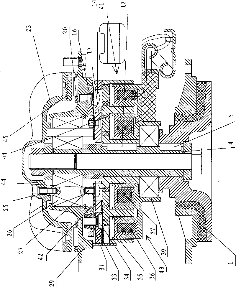
[0018] The specific structure and working principle of the present invention will be further described below in conjunction with the accompanying drawings.

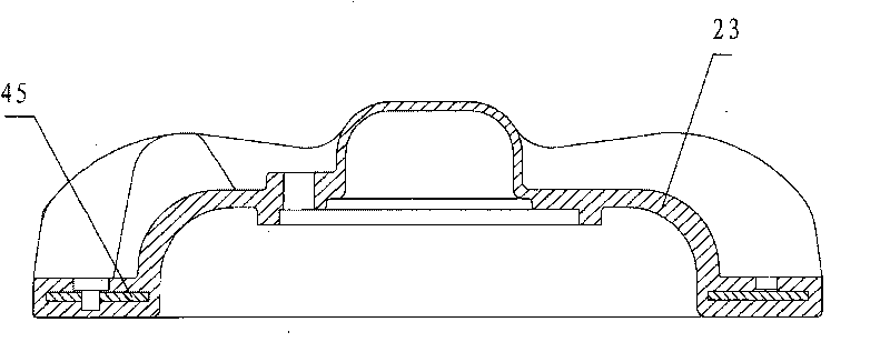
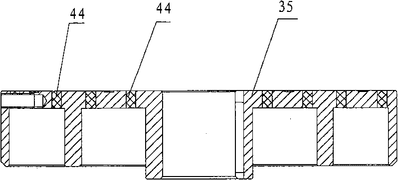
[0019] See attached Figure 1-3 As shown, an electromagnetic fan clutch realizes two-stage rotation speed conversion by using floating magnetic transmission and friction transmission, and mainly includes clutch rotor 41, clutch plate 42, excitation coil 43, fan base 29, transmission member 23, clutch rotor 41 has an electromagnetic coil seat 39 and an electromagnetic inductor 35 coaxially fixed with the rotating main shaft 4, the electromagnetic inductor 35 is located above the electromagnetic coil seat 39, and the clutch plate 42 includes a ring-shaped ring arranged along the radial direction of the clutch rotor 41. Inner clutch plate 17 and outer clutch plate 33, in attached figure 1 Among them, the inner clutch plate 17 and the outer clutch plate 33 are opposite to the electromagnetic inductor 35, and are located abov...


PUM


Abstract

The invention discloses an electromagnetic fan clutch which comprises a clutch rotor, an internal clutch plate, an external clutch plate, a built-in coil, an external coil, a fan pedestal and a driving part, wherein the internal clutch plate and the external clutch plate are arranged opposite to the clutch rotor, the built-in coil and the external coil are positioned in the clutch rotor, the driving part and the fan pedestal are in driving connection, and the fan pedestal and the driving part are respectively connected with the internal clutch plate and the external clutch plate. Because the clutch rotor is provided with a copper ring for insulating an electromagnetic force, when the built-in coil and the external coil are respectively electrified, the internal clutch plate and the external clutch plate can be only sucked, and the torque of the clutch rotor is respectively correspondingly transmitted onto the driving part or the fan pedestal; when the torque is directly transmitted onto the fan pedestal, a fan is rotated at a high speed; and when the torque is transmitted onto the driving part, the fan is driven to rotate at a low speed under the action of the floating magnetic force between an iron part and a magnetic pole, so that the clutch has double-stage rotating speeds and corresponds to different radiating requirements, which is beneficial to saving energy and improving the fuel economical property.

Description

technical field [0001] The invention relates to an electromagnetic clutch, in particular to an electromagnetic clutch used for fan control on automobiles. Background technique [0002] At present, the electromagnetic clutch used for the cooling fan on the automobile engine is mainly composed of the clutch rotor, the clutch plate opposite to the clutch rotor, the excitation coil, and the fan base for connecting the fan. The excitation coil is located in the clutch rotor. When the current is supplied, the coil Magnetic lines of force are generated in the clutch rotor and the clutch plate to attract the clutch plate to the clutch rotor, and the clutch plate is connected to the fan base through the spring plate. When the coil is energized, the electromagnetic force generated overcomes the elastic force of the spring plate, so that the clutch plate is attracted to the clutch rotor. Using the friction force between the clutch plate and the clutch rotor, the fan base rotates with t...

Claims


Application Information

Patent Timeline
IPC IPC(8): F01P7/12F16D27/02
CPCY02T10/76
Inventor 龚达锦
Owner SUZHOU RISING AUTO PARTS
Why Eureka
Try Eureka