Supercharge Your Innovation With Domain-Expert AI Agents!

Direction sensing circuit and electronic device applying same

An electronic device and direction sensing technology, which is applied in the field of direction sensing circuits and electronic devices, can solve the problems of occupying the input end of the processor and increasing the difficulty of processor design, and achieve the effect of avoiding misoperation and multi-application

Inactive Publication Date: 2010-06-23
HONG FU JIN PRECISION IND (SHENZHEN) CO LTD +1
View PDF0 Cites 3 Cited by
  • Summary
  • Abstract
  • Description
  • Claims
  • Application Information

AI Technical Summary

Problems solved by technology

However, when the above-mentioned direction sensing circuit 10 is applied to an electronic device, it can only detect three placement orientations. Generally, an electronic device has four placement orientations, so it cannot meet such requirements.
[0004] The more common way to solve the above problems is to increase the input terminal (I0 port) of the processor for connecting the pin of the direction sensing circuit, which will take up too many input terminals of the processor and increase the design difficulty of the processor

Method used


Image

  • Direction sensing circuit and electronic device applying same
  • Direction sensing circuit and electronic device applying same
  • Direction sensing circuit and electronic device applying same

Examples


Embodiment Construction

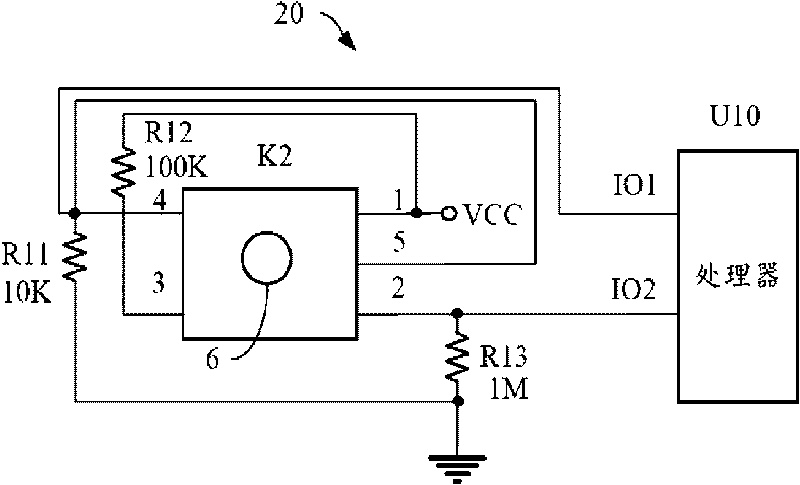
[0015] Please refer to figure 1 , figure 1 It is a hardware architecture diagram of the direction sensing circuit of the present invention. The circuit 20 includes a ball switch K2, a processor U10, a first resistor R11, a second resistor R12 and a third resistor R13. The resistance values ​​of the first, second and third resistors increase sequentially. In this embodiment, the resistance value of the first resistor R11 is, for example, 10K ohms, the resistance value of the second resistor R12 is, for example, 100K ohms, and the resistance value of the third resistor R13 is, for example, 1M ohms . The processor U10 includes a first input terminal IO1 and a second input terminal IO2. The ball switch K2 includes a first pin 1 , a second pin 2 , a third pin 3 , a fourth pin 4 , a fifth pin 5 and a ball 6 . The first pin 1 is electrically connected to a power supply Vcc, and is electrically connected to the third pin 3 via the second resistor R12; the second pin 2 is electr...


PUM


Abstract

The invention provides a direction sensing circuit, comprising a processor, a ball switch, a first resistor, a second resistor and a third resistor, wherein the processor comprises a first input end and a second input end, and the ball switch comprises a first pin, a second pin, a third pin, a fourth pin and a fifth pin. The resistance of the third resistor is far more than that of the second resistor and the resistance of the second resistor is far more than that of the first resistor. A ball is electrically connected with different pins according to the difference of the placement directions of the ball switch so as to ensure the first input end and the second input end of the processor to be in different combined input states. The processor is used for storing a list of control signals corresponding to the combined input states of the first input end and the second input end, outputting corresponding control signals according to the combined input states of the first input end and the second input end and executing direction control according to the control signals. The invention also provides an electronic device applying the circuit.

Description

technical field [0001] The invention relates to a direction sensing circuit and an electronic device using the circuit. Background technique [0002] Currently, more and more electronic devices use direction sensing circuits to realize corresponding functions. For example, in a digital photo frame, the direction sensing circuit is used to control the state of displaying images or in other electronic devices to perform other control functions. [0003] Figure 4 It is a hardware structure diagram of the direction sensing circuit 10 in the prior art. The direction sensing circuit 10 includes a ball switch K1, a processor U1 and resistors R1, R2. The ball switch K1 includes a first pin 1 , a second pin 2 , a third pin 3 , a fourth pin 4 and a ball 6 . The processor U1 includes a first input terminal IO1 and a second input terminal IO2. The first pin 1 is electrically connected to the first input terminal IO1, and is electrically connected to a power supply VCC through the r...

Claims


Application Information

Patent Timeline
Patent Type & Authority Applications(China)
IPC IPC(8): G06F3/01G06F3/048G01P13/02
CPCG01R31/2813
Inventor 蒋万军董婷
Owner HONG FU JIN PRECISION IND (SHENZHEN) CO LTD
Features
  • R&D
  • Intellectual Property
  • Life Sciences
  • Materials
  • Tech Scout
  • Unparalleled Data Quality
  • Higher Quality Content
  • 60% Fewer Hallucinations
Learn More