Cast-in-place anti-cracking and earthquake-resistant floor system for storied building

An anti-earthquake and floor covering technology, applied in the on-site preparation of floor slabs and building components, formwork/template/work frame, etc., can solve problems such as unreasonable structure, uneven bottom surface, poor economy, etc. Improve the overall anti-crack and maintain the effect of stability

Inactive Publication Date: 2012-08-08
HUNAN BDF ENERGY SAVING TECH
View PDF1 Cites 0 Cited by
  • Summary
  • Abstract
  • Description
  • Claims
  • Application Information

AI Technical Summary

Problems solved by technology

[0005] In order to solve the problems of uneven bottom surface, complex process, unreasonable structure and poor economy of existing floors, the present invention provides a high-strength, simple process, reasonable structure, light weight, and can realize large-span cast-in-place anti-cracking Earthquake-resistant floor

Method used


Image

  • Cast-in-place anti-cracking and earthquake-resistant floor system for storied building
  • Cast-in-place anti-cracking and earthquake-resistant floor system for storied building
  • Cast-in-place anti-cracking and earthquake-resistant floor system for storied building

Examples


Embodiment 1

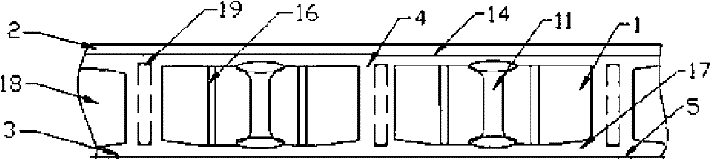
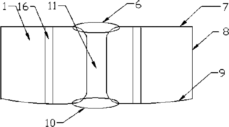
[0025] With reference to the accompanying drawings, the bottom plate 9 and the frame body 8 of the hollow body 1 are made in the mold at one time, generally using special cement to pour, and a class of linings such as glass fiber filaments, glass fiber cloth, and steel wire mesh are added in the middle of the special cement. To enhance the firmness and compression resistance of the hollow body 1, two or three or four arcs 15 protruding outward are made on the bottom surface of the mold. The barbed wire 3 laid between the edge plates 17 is in point contact, and the multi-arc shape can make the bottom 9 of the hollow body 1 form a channel infiltrated into the concrete mortar. This scheme can realize the smooth bottom surface of the lower flange plate 17. The arcs of the bottom surface of the hollow body 1 are symmetrically arranged, and the size of the arc 15 can be adjusted with the size of the hollow body 1. It should be as large as possible under the premise of ensuring the pa...

Embodiment 2

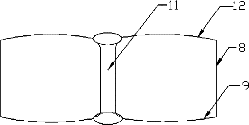
[0028] Using the same pouring method as above, in some buildings where the load-bearing requirements of the floor are not large, foam plastic blocks can be used to make the hollow body 1. The body style is the same, the middle is solid foam plastic, and the through channel 11 in the middle is realized by reserving or digging through the foam plastic block. When installing this hollow body, the bottom of the hollow body of the foam plastic block cannot be directly placed on the building template 5 Above, it should be more than 3 millimeters away from the building formwork 5, and the height of the arc-shaped protrusion 15 of the bottom plate 9 is less than the thickness of the lower flange plate of the floor and less than 18 millimeters.


PUM


Abstract

The invention discloses a cast-in-place anti-cracking and earthquake-resistant floor system for a stored building, which comprises hollow layers, a top flange plate above the hollow layers, a bottom flange plate below the hollow layers, ribbon strips between the hollow layers, a floor system template, and hollow bodies, wherein the hollow layers are formed by concrete mortar and reinforcing steelbars; the floor system template is used for supporting the bottom flange plate; the hollow bodies are cast in the hollow layers, the outer surfaces of the soleplates of the hollow bodies are at leastprovided with two arc-shaped bulges; a lining material such as a steel wire gauze or glass fiber cloth is arranged between each soleplate of the hollow bodies and the floor system template; distance between arc-shaped lower surfaces of the hollow bodies and the floor system template is greater than 3 millimeters; and the hollow bodies are fixed on the bottom flange plate or the ribbon strips through fixing parts. The cast-in-place anti-cracking and earthquake-resistant floor system for the storied building has the characteristics of simple and convenient construction, light weight, and good anti-cracking and earthquake-resistant effects; and therefore, the cast-in-place bottom surface of a floor system is smooth.

Description

[0001] This application is a divisional application of a patent application with an application date of July 9, 2008, an application number of 200810133186.2, and an invention title of "A Cast-in-situ Floor for Buildings". technical field [0002] The invention relates to a building component, in particular to a cast-in-place anti-crack and anti-seismic slab of a building. Background technique [0003] At present, most of the buildings with brick-concrete structure and frame structure use prefabricated hollow slabs as floor slabs. This kind of floor slab has the advantages of fast construction speed and low cost, but because there is no firm connection between two adjacent prefabricated hollow slabs , Only cement mortar is used to fill the joints, so the integrity is poor, which is not conducive to earthquake resistance, and cracks and water seepage often occur. There are also some cast-in-place concrete floor technology, using the prepared formwork components and reinforced...

Claims


Application Information

Patent Timeline
Patent Type & Authority Patents(China)
IPC IPC(8): E04B5/36E04B5/18E04G15/06
Inventor 王本淼王海崴肖曙光
Owner HUNAN BDF ENERGY SAVING TECH
Why Eureka
Try Eureka