Hollow body of cast-in-situ hollow superstructure

A hollow floor and hollow body technology, applied in the field preparation of floors and building components, formwork/formwork/working frames, etc., can solve problems such as unsatisfactory, increase weight, enhance resistance, and improve earthquake resistance cracking effect

Inactive Publication Date: 2010-06-30
王本淼
View PDF4 Cites 9 Cited by
  • Summary
  • Abstract
  • Description
  • Claims
  • Application Information

AI Technical Summary

Problems solved by technology

[0009] But still do not satisfy people to adopt large dense rib hollow floor to set the flange thin bottom plate, realize the smooth roof and economy of the cast-in-place c

Method used


Image

  • Hollow body of cast-in-situ hollow superstructure
  • Hollow body of cast-in-situ hollow superstructure
  • Hollow body of cast-in-situ hollow superstructure

Examples


Embodiment Construction

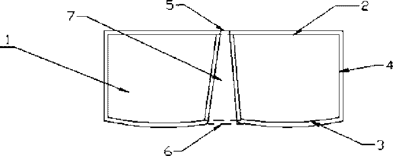
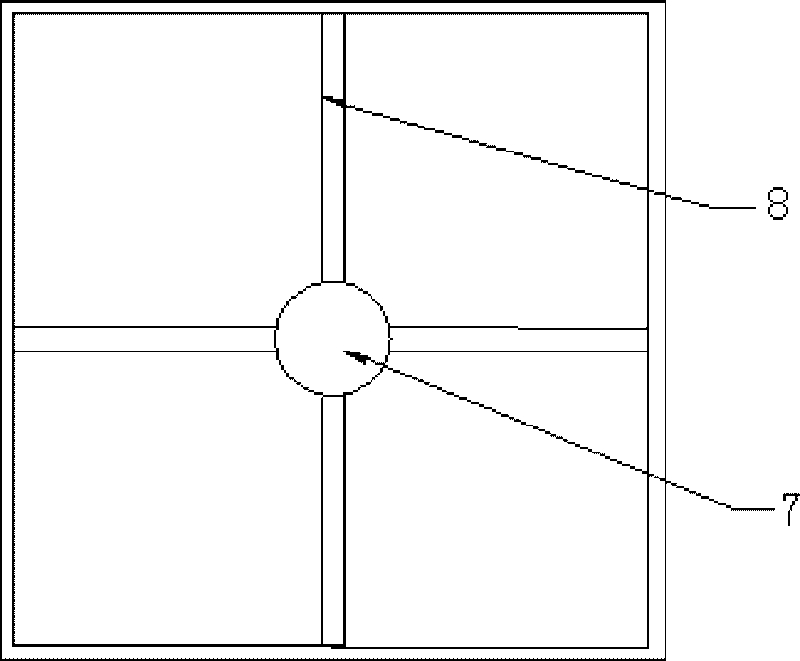
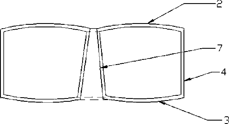
[0025] The present invention will be further described now in conjunction with accompanying drawing, as figure 1 As shown, the hollow body 1 in this program is composed of a bottom plate 3, a middle frame 4 and a capped top cover 2. The top cover 2 is manufactured separately and has a hole 5 on it. The bottom plate 3 and the frame body 4 of the hollow body 1 pass through The mold is molded at one time, and two arcs are formed at the bottom of the mold, and multiple arcs can also be made as required. The bottom surface of the mold is left with a hole-making column in the concave part between the arc and the arc. The position is opposite to the hole 5 on the top cover 2, and the corresponding pipe 7 is installed on the hole 6 of the bottom plate 3, and the other end of the pipe 7 is connected to the hole 5 on the top cover 2, and some supporting top covers are placed on the bottom plate 3 as required Columns, such as plastic and wooden columns, can also be poured with concrete m...


PUM


Abstract

The invention relates to a hollow body of a cast-in-situ hollow superstructure, which comprises a bottom board (3), a frame body (4) and a top cover (2). The hollow body of the cast-in-situ hollow superstructure is characterized in that the outer surface of the bottom board (3) is provided with at least two arc-shaped bulges, holes (5) and (6) are respectively arranged on the bottom board and the top cover, and the holes of the bottom board and the top cover are connected by a sealed penetration passage (7); the penetration passage (7) is in a horn shape from top to bottom; the hollow body is integrally sealed, and the penetration passage (7) and the frame body (4) are in a sealed state; and a supporter is arranged between the bottom board (3) and the top cover (2). The superstructure adopting the hollow body has the characteristics of light weight, large hardness, crushing resistance, crack prevention, vibration resistance and the like.

Description

[0001] This application is a divisional application with an application date of June 20, 2008, an application number of 200810115294.7, and an invention title of "A Hollow Body for Cast-in-situ Vierifice Floor". technical field [0002] The invention relates to a building floor component, in particular to a hollow body of a hollow floor. Background technique [0003] The conventional long-span building structure system is realized by setting beams, increasing the thickness of the slab, and applying prestress. All of them have large foundation loads, poor shock resistance, and high costs. Requirements for long-span building structures. [0004] In his early utility model patent No. ZL98231113.3, the applicant disclosed a concrete thin-walled cylindrical member. Using this member successfully solved the technical problem of non-core-pulling hole forming of the cast-in-place hollow floor, which can greatly Reduce the weight of the foundation load, enhance the earthquake resist...

Claims


Application Information

Patent Timeline
IPC IPC(8): E04B5/36E04B5/18E04G15/06
Inventor 王本淼王海崴肖曙光
Owner 王本淼
Why Eureka
Try Eureka