Supercharge Your Innovation With Domain-Expert AI Agents!

Connection method and connection structure of regulating transformer and power transformer

A technology for voltage regulating transformers and power transformers, applied in the field of transformers, can solve the problems of large amount of transformation of transformer shells, affecting the stability of transformers, and large amount of transformation projects, achieving good promotion and use value, simple structure, and saving construction time. Effect

Active Publication Date: 2013-03-27
GUIZHOU NANYUAN ELECTRIC POWER TECH
View PDF0 Cites 0 Cited by
  • Summary
  • Abstract
  • Description
  • Claims
  • Application Information

AI Technical Summary

Problems solved by technology

[0002] There are many ways to transform the off-load tap-changing transformer, one of which is to install a tap-regulating transformer on the existing off-load tap-changing transformer, which involves the connection of two transformers, because The connection of existing transformers is mostly top connection, which is to set a bushing connected to the transformer coil on the top of the transformer, and then connect to the bushing on the transformer through a wire (cable); but in the actual transformation process, it is found that this connection method There are the following problems: a. There are already 11 bushings on the upper part of the existing transformer, and the wire connections are very dense. Adding 3 more bushings for the connection of the two transformers on the basis of the original number of top bushings will lead to a large amount of reconstruction work Large, labor-intensive, and time-consuming; b. It will lead to more dense cables on the top of the transformer, which is likely to cause accidents; c. The addition of bushings requires a lot of transformation of the transformer shell, which affects the stability of the transformer; d. Add 6 bushings , higher cost

Method used


Image

  • Connection method and connection structure of regulating transformer and power transformer

Examples


Embodiment

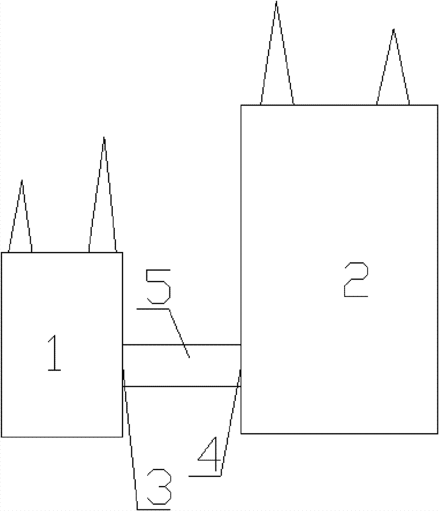
[0011] Example: as figure 1 As shown, a high-voltage terminal connection hole 3 is opened on the side of the voltage regulating transformer 1, and a secondary coil connection hole 4 is opened on the side of the power transformer 2. The high-voltage terminal connection hole 3 is opposite to the secondary coil connection hole 4. A wire 5 is connected to the high-voltage side coil of the transformer 1, and the wire 5 is connected to the secondary coil in the power transformer 2 after passing through the high-voltage terminal connection hole 3 and the secondary coil connection hole 4. The wire 5 is a three-phase wire, and the used The conductor 5 is an oil-filled busbar, an inflatable busbar or a cable. In this example, an oil-filled busbar filled with transformer oil is preferred. At the same time, a flexible segment conductor is provided on the conductor 5, so that when the foundation on which the transformer is placed changes, the flexible segment conductor can be used for the t...


PUM


Abstract

The invention discloses a connection method and connection structure of a regulating transformer and a power transformer. The method is that a high-voltage terminal port is arranged on the side of the regulating transformer, a secondary coil connection hole is arranged on the opposite side of the power transformer and the regulating transformer, and meanwhile wires which pass through the high-voltage terminal port and the secondary coil connection hole are used to connect the interior elements of the regulating transformer and the interior elements of the power transformer. In the method of the invention, when the two transformers are connected, tapping on the top of the transformers and arranging sleeves are not needed, the problem of rearranging the wires on the top of the transformers are unnecessary to consider, the modification can be completed within two hours according to the statistics of the applicant of the invention; and during the modification process, the damage of the shells of the transformers is smaller, the exposing time of the interior elements of the transformers is shorter and the performance stability of the transformers can be ensured after the modification.

Description

technical field [0001] The invention relates to a transformer, in particular to a connection method and a connection structure between a voltage regulating transformer and a power transformer. Background technique [0002] There are many ways to transform the off-load voltage regulating transformer, one of which is to install a voltage regulating transformer on the existing off-load voltage regulating transformer. This transformation method involves the connection of two transformers. The connection of the existing transformer is mostly top connection, which is to set a bushing connected to the transformer coil at the top of the transformer, and then connect it to the bushing on the transformer through a wire (cable); but this connection method was found in the actual transformation process. There are the following problems: a. There are already as many as 11 upper bushings on the existing transformer, and the wire connections are very dense. On the basis of the original num...

Claims


Application Information

Patent Timeline
Patent Type & Authority Patents(China)
IPC IPC(8): H01F27/28H01F41/00
Inventor 焦通高欣罗飞
Owner GUIZHOU NANYUAN ELECTRIC POWER TECH
Features
  • R&D
  • Intellectual Property
  • Life Sciences
  • Materials
  • Tech Scout
  • Unparalleled Data Quality
  • Higher Quality Content
  • 60% Fewer Hallucinations
Learn More