Rail system and monorail system

A technology for rails and rail joints, which is applied in the field of rail systems, can solve problems such as high production costs, and achieve the effect of avoiding impact

Active Publication Date: 2010-06-30
SEW-EURODRIVE GMBH & CO KG
View PDF0 Cites 10 Cited by
  • Summary
  • Abstract
  • Description
  • Claims
  • Application Information

AI Technical Summary

Problems solved by technology

However, this fixation requires high production costs

Method used


Image

  • Rail system and monorail system
  • Rail system and monorail system
  • Rail system and monorail system

Examples


Embodiment Construction

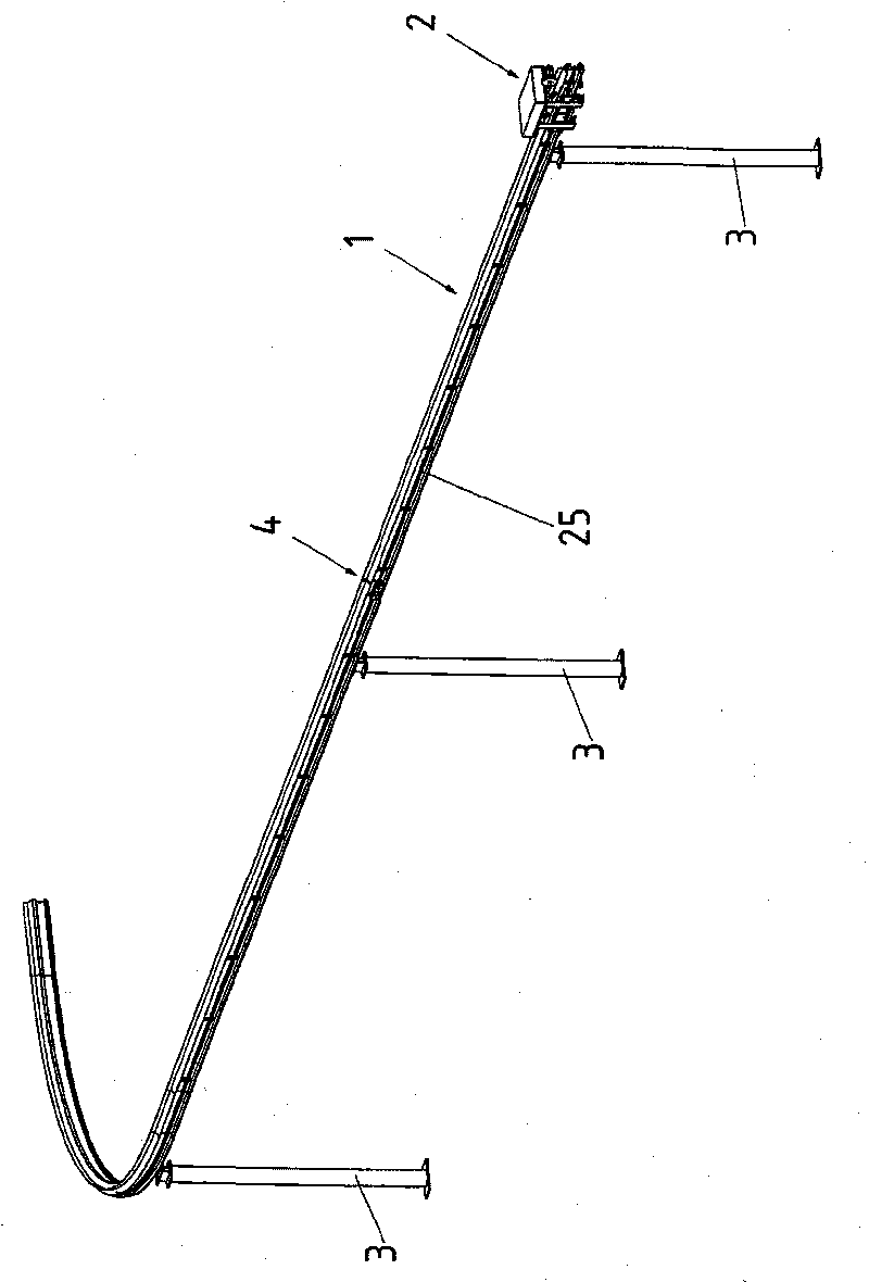
[0083] figure 1A portion of a monorail line system is shown. Vehicle 2 is movable on track 1 . Track 1 is fixed on pillar 3. The fastening area of ​​each strut 3 extends over a length that is smaller than the distance between adjacent struts 3 . This fixation in each case allows a region of the rail 1 to vibrate torsionally about the axis of the strut 3 . The rail 1 is formed from a profile having a greater flexural strength in a first, vertical direction than in a second, horizontal direction. Thus, the preferred vibration direction of the rail 1 between two adjacent struts 3 lies in the horizontal plane, transverse to the direction of extension of the rail 1 .

[0084] Rail 1 of the rail system is designed as an aluminum bar profile.

[0085] The linear distance between two adjacent struts is at least 10 m, preferably 12 m. The track 1 is laid such that, under typical wind forces at the application site, wind-induced vibrations are excited with a maximum deflection of ...


PUM


Abstract

In a rail system (70), the rail joints (4) are bridged by a connecting element (52, 64, 74, 77), wherein the rail ends (5a, 5b, 72, 73) are oriented flush with one another and can be displaced in the direction of the rails. The rails (71) and the connecting element (52, 64, 74, 77) are embodied in such a way that no interruption is produced in running faces at the rail joint (4).

Description

technical field [0001] The invention relates to a rail system for a rail vehicle movable in a rail direction, wherein the rail system comprises at least one rail having at least one rail joint on which two rail ends rest The invention also relates to a monorail line system. Background technique [0002] Such track systems are known in railway technology, in which track joints are provided to compensate for the longitudinal expansion of the track when heated. The rails that meet at the rail joint are fastened to the support or holder by means of clips or the like arranged at narrow distances in the direction of the rails and are thus substantially immovable relative to one another, but are fixed in alignment. However, such fastening requires high production costs. Contents of the invention [0003] The object of the present invention is to improve a monorail system in which production costs are to be reduced. [0004] According to the invention, this object is achieved b...

Claims


Application Information

Patent Timeline
Patent Type & Authority Applications(China)
IPC IPC(8): B61B13/04
CPCB61C13/04B61B13/04
Inventor G·贝克尔J·施密特
Owner SEW-EURODRIVE GMBH & CO KG
Why Eureka
Try Eureka