Electro-dynamic tether based satellite deorbit device and method thereof

An electric power and satellite technology, applied in the field of satellite deorbit devices, can solve the problems of high deorbit cost and low deorbit efficiency, and achieve the effects of high deorbit efficiency, good effect and cost reduction.

Inactive Publication Date: 2010-07-07
HARBIN INST OF TECH
View PDF0 Cites 26 Cited by
  • Summary
  • Abstract
  • Description
  • Claims
  • Application Information

AI Technical Summary

Problems solved by technology

[0004] The present invention aims to solve the problem of high de-orbiting cost and low de-orbiting efficiency of the atmospheric resistance de-orbiting method in the existing propellant de-orbiting method, thereby providing a satellite de-orbiting device and method based on electrodynamic tethers

Method used


Image

  • Electro-dynamic tether based satellite deorbit device and method thereof
  • Electro-dynamic tether based satellite deorbit device and method thereof
  • Electro-dynamic tether based satellite deorbit device and method thereof

Examples


specific Embodiment approach 1

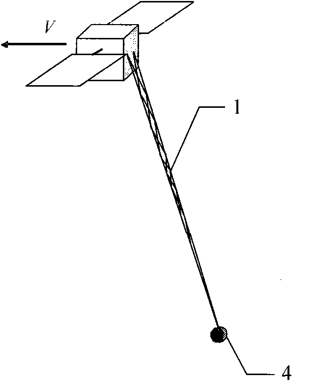
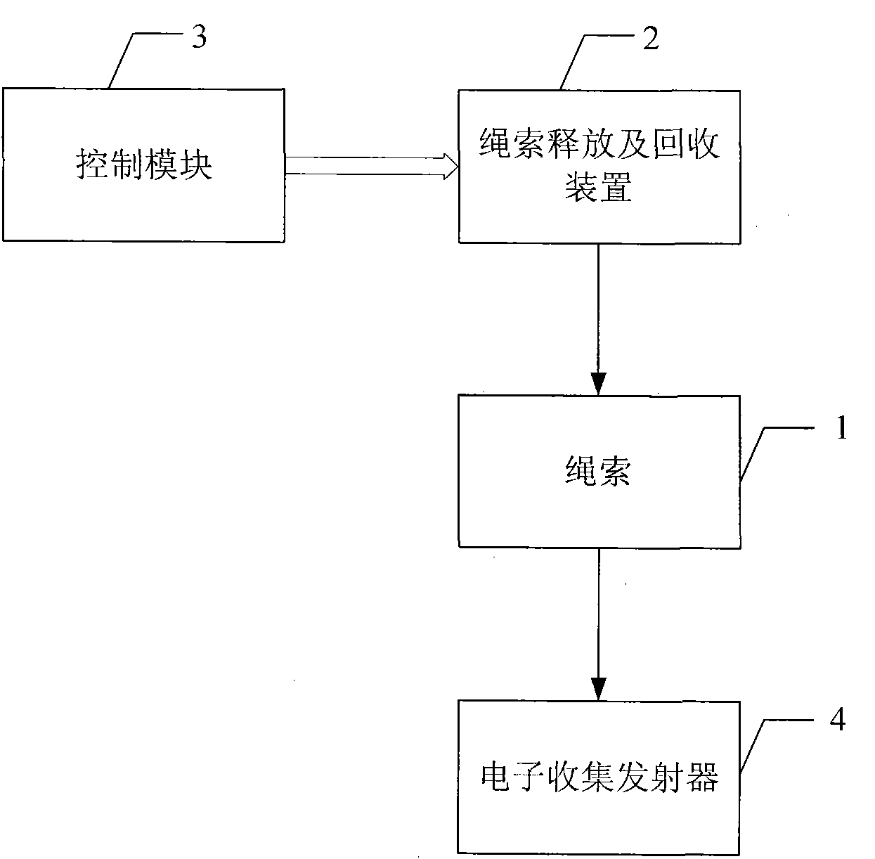
[0023] Specific implementation mode 1. Combination figure 1 with figure 2 Describe this specific embodiment, a kind of satellite deorbiting device based on electric power tether, it is made up of rope 1, rope release and recovery device 2, control module 3 and electron collection transmitter 4, and described rope 1 is made of insulating rope section It is composed of a conductive rope segment; the control signal output end of the control module 3 is connected to the control signal input end of the rope release and recovery device 2, and the end of the insulating rope segment of the rope 1 is fixed on the rope release and recovery device 2, and the rope 1 The end of the conductive rope section is connected with the electron collection emitter 4.

[0024] Working principle: The functions of the four parts of the hardware equipment of the electrodynamic tethered off-orbit system are as follows: Most of the rope 1 is a bare wire, which can collect electrons from the plasma in th...

specific Embodiment approach 2

[0030] Embodiment 2. The difference between this embodiment and the satellite de-orbiting system based on electrodynamic tethers described in Embodiment 1 is that the conductive rope section of the rope 1 is a mesh structure made of aluminum wires.

[0031] This specific embodiment adopts a mesh structure, which has a higher survivability than ropes with a single-strand or double-strand structure.

[0032] This embodiment can provide multiple paths to disperse mechanical loads and currents, and can provide high survivability for several weeks or months to the electric power tether flying in the space debris environment, so as to achieve the purpose of deorbiting.

specific Embodiment approach 3

[0033] Embodiment 3. The difference between this embodiment and the satellite de-orbiting system based on electrodynamic tethers described in Embodiment 1 or 2 is that the insulating rope section of the rope 1 has high compressive capacity and strong insulation performance composites.

[0034]This embodiment can ensure that the rope will not be broken after being released, and can also insulate the rope from the satellite.


PUM


Abstract

The invention provides an electro-dynamic tether based satellite deorbit device and a method thereof, relating to the satellite deorbit device and the method thereof. The device and the method solve the problems of high deorbit cost of a propellant deorbit method and low deorbit efficiency of an atmospheric drag deorbit method. In the system, a control signal output end of a control module is connected with a control signal input end of a tether releasing and reclaiming device; the tail end of an insulating tether section of the tether is fixed on the tether releasing and reclaiming device; and the tail end of a conductive tether section of the tether is connected with an electron collection transmitter. The method comprises the following steps: determining longitude, latitude and height of the position of a satellite at current time according to six factors of the initial orbit of the satellite to acquire the magnetic field strength of the current position; calculating the Lorentz force generated by the tether; resolving the Lorentz force along the radial direction, the tangential direction and the outerplanar direction to acquire the orbit six factors at next time, and determining a new height of the satellite orbit; and circulating the steps until the height of the satellite is less than or equal to 120km to complete the satellite deorbit process. The device and the method are applicable to the satellite deorbit process.

Description

technical field [0001] The invention relates to a satellite off-orbit device and method. Background technique [0002] As of 2002, there were 2 million kilograms of space debris and abandoned aircraft. Recent studies have shown that if no measures are taken, space debris will increase at a rate of 5% per year, especially at orbital altitudes between 500km and 2000km. The debris in the earth's orbit has been increasing year by year for quite a long time, and the possibility of a normal working aircraft colliding with space debris is increasing year by year, which puts human space activities at great risk. This is not only due to collisions between debris and orbiting satellites, but also due to the creation of new debris after collisions, resulting in an exponential increase in the number of debris. This is an even bigger problem for satellites launched in the future, especially those that make up constellations. On February 10, 2009, the Russian abandoned satellite "Cosmos...

Claims


Application Information

Patent Timeline
Patent Type & Authority Applications(China)
IPC IPC(8): B64G1/10
Inventor 孔宪仁徐大富
Owner HARBIN INST OF TECH
Why Eureka
Try Eureka