Bearing roller for rolling mill

A bearing roller and roller technology, applied in bearing components, shafts and bearings, mechanical equipment, etc., can solve the problems affecting the service life of bearings, shortage of fitting surfaces, bearing vibration, etc., to reduce the wear area, reduce wear, The effect of enhancing the usability

Inactive Publication Date: 2010-07-07
DALIAN QUANXIN ROLLING MILL BEARING MFGCO
View PDF0 Cites 0 Cited by
  • Summary
  • Abstract
  • Description
  • Claims
  • Application Information

AI Technical Summary

Problems solved by technology

The problem is that due to the large contact area between the rib and the end face of the cylindrical roller, when the bearing under high-speed operation rotates, the area is large due to increased wear, which in turn affects the service life of the bearing
[0003] In addition, the contact between the rolling surface of the cylindrical roller and the raceways of the inner and outer rings gradually produces a shortage of fitting surfaces with wear and tear, resulting in vibration and instability of the bearing during rotation

Method used


Image

  • Bearing roller for rolling mill
  • Bearing roller for rolling mill

Examples


Embodiment Construction

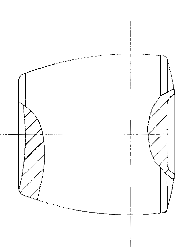
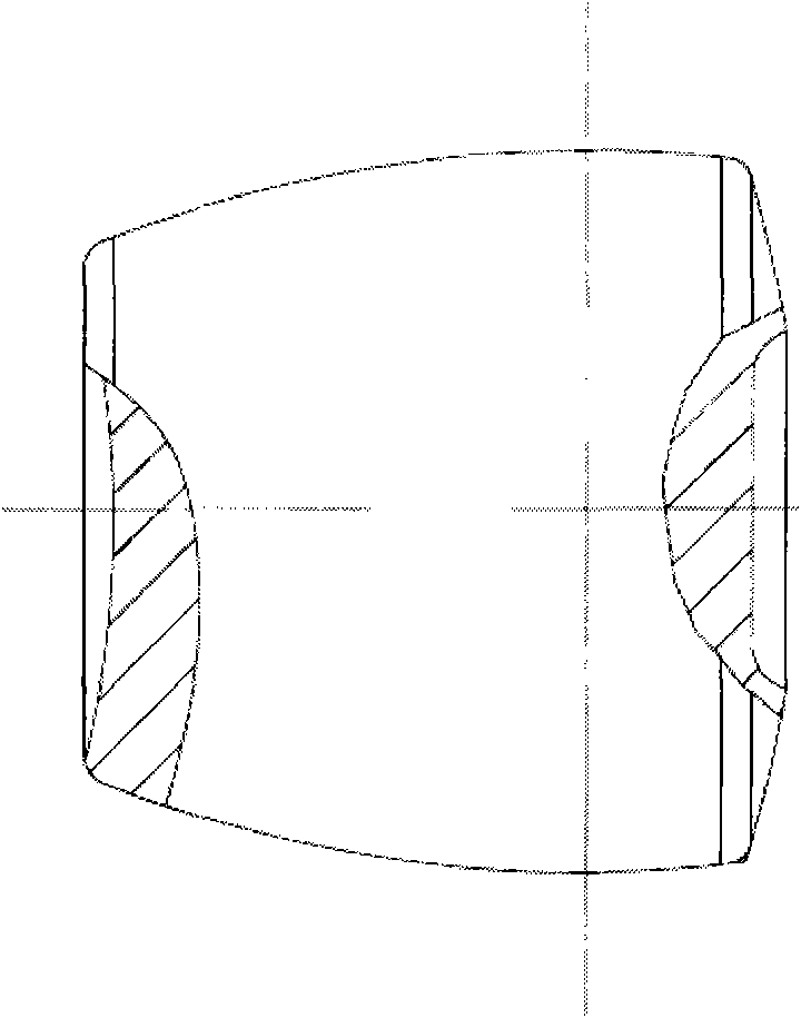
[0008] refer to figure 1 In the bearing roller provided by the present invention, the rolling surface of the roller is a rotary surface structure formed by turning a straight arc around the center line; the straight arc is inclined, so that the two sides of the roller form a large end face with a large cross-sectional area and a large cross-sectional area. Small facets. The bearing of the present invention is mainly used in rolling mills. In the figure, there are rounded corners at the edges of the end surfaces on both sides of the roller. In addition if figure 1 The shaded part on the right side is partially sectioned, the center of the large end surface is provided with a circular flat-bottomed groove, and the groove wall is in the form of a concave arc surface transition. The partial cross-sectional structure of the shaded part on the left side of the figure shows that the small end surface forms a spherical groove from the edge to the center.


PUM


Abstract

The invention discloses a bearing roller for a rolling mill, the rolling surface of a roller is a revolution surface structure formed by revolving around a central line by a straight circular arc; a straight circular arc inclination state leads two sides of the roller to form a large end surface with large cross section and a small end surface with small cross section; the edge positions of the end surfaces at two sides of the roller are rounded off; a circular arc flat-bottomed groove is arranged at the central position of the large end surface, and the wall of the groove is an indented circular surface transitional form, and the small end surface forms a spherical surface groove from edge to center; the bearing roller in the invention is located axially, only pushing parts are arranged in the indented positions of the end surface at two sides, thereby not only reducing the abrasion area of the roller end surface and the traditional check ring, reducing the abrasion and improving the service life of the bearing, but also enhancing the thickness of the roller and the abrasive resistance owning to a circular arc rotational structure of the rolling surface.

Description

technical field [0001] The technology relates to a roller for a bearing. Background technique [0002] In the prior art, cylindrical rollers mostly rely on ribs to limit the rollers in the axial direction of the bearing. The problem is that due to the large contact area between the rib and the end face of the cylindrical roller, when the bearing under high-speed operation rotates, the large area will increase the wear and tear, which will affect the service life of the bearing. [0003] In addition, the contact between the rolling surface of the cylindrical roller and the raceways of the inner and outer rings gradually produces a shortage of fitting surfaces with wear and tear, resulting in vibration and instability of the bearing during rotation. Contents of the invention [0004] The present invention aims to provide durable, wear-resistant bearing rollers and thus increase the service life of the bearing. [0005] The invention provides a bearing roller for a rolling ...

Claims


Application Information

Patent Timeline
Patent Type & Authority Applications(China)
IPC IPC(8): F16C33/36
Inventor 陶永强何华孙德忠林永浩孙玉江
Owner DALIAN QUANXIN ROLLING MILL BEARING MFGCO
Why Eureka
Try Eureka