Automatic switching circuit for voltage and current measurement and method thereof

An automatic switching, voltage and current technology, applied in the direction of using digital measurement technology for measurement, etc., can solve the problems of complicated manual switching modes, and achieve the effect of full utilization and convenient use

Active Publication Date: 2010-07-07
ZHUZHOU CSR TIMES ELECTRIC CO LTD
View PDF0 Cites 32 Cited by
  • Summary
  • Abstract
  • Description
  • Claims
  • Application Information

AI Technical Summary

Problems solved by technology

[0002] The general data acquisition module can only collect voltage signals or current signals fixedly. If the data acquisition circuit is added such as figure 1 The voltage / current measurement mode switching circuit shown can collect both voltage signals and current signals in a system, but the switching between these two test modes needs to be done manually, that is, the tester needs to be turned on. Cover, connect the jumper sleeve at the voltage / current switching circuit to the circuit in the voltage test mode or current test mode, and then cover the tester cover. If the type of the collected signal changes next time, repeat The above process, therefore, the original manual switching mode is more complicated

Method used


Image

  • Automatic switching circuit for voltage and current measurement and method thereof
  • Automatic switching circuit for voltage and current measurement and method thereof
  • Automatic switching circuit for voltage and current measurement and method thereof

Examples


Embodiment Construction

[0026] The accompanying drawings show specific embodiments of the present invention, and the present invention will be further described below through the accompanying drawings and the embodiments.

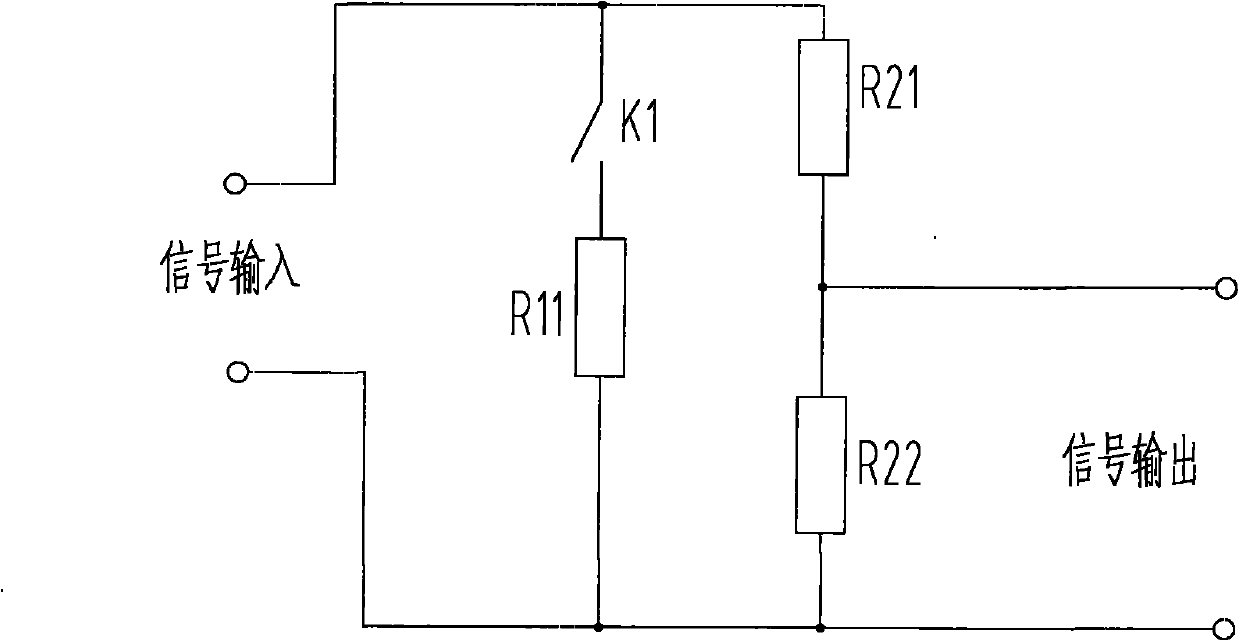
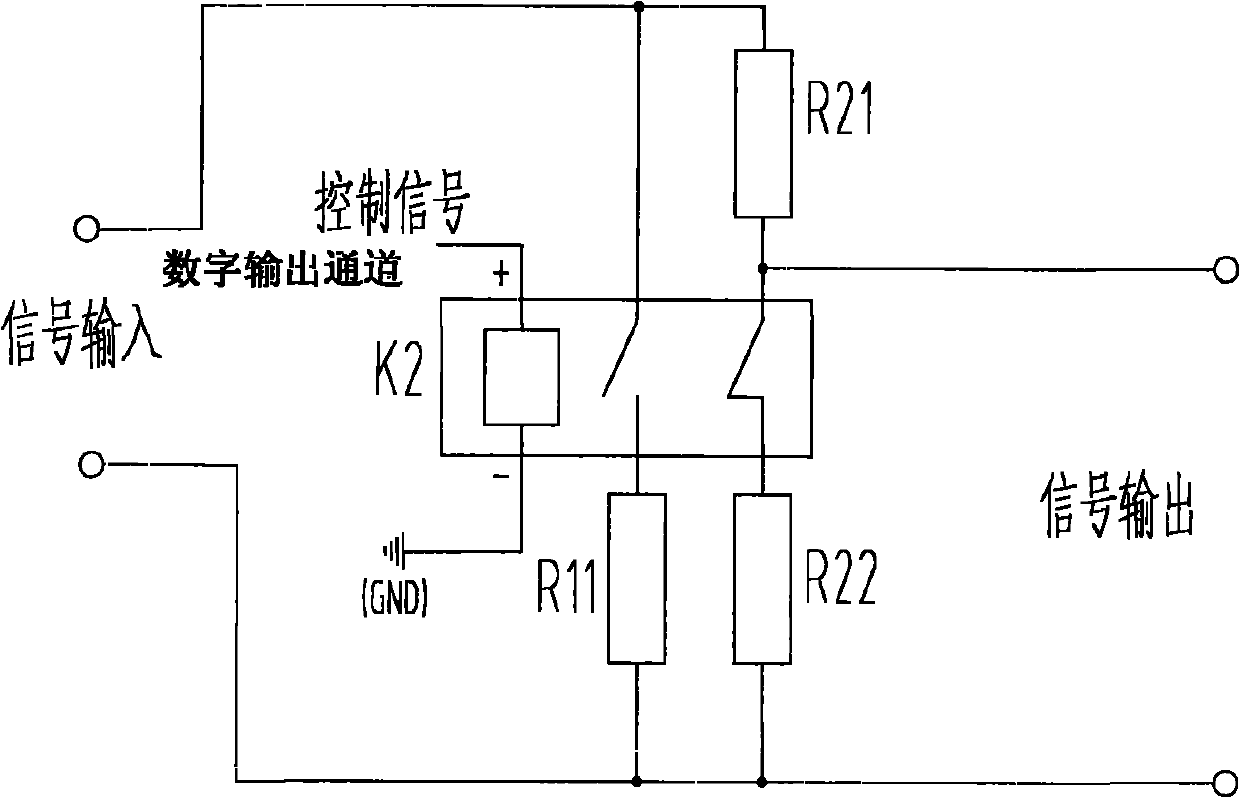
[0027] As a specific implementation of the voltage and current measurement automatic switching circuit of the present invention, take the MP425 data acquisition module as an example, the MP425 data acquisition module is a USB2.0 interface, 14-bit AD acquisition module, with 8 synchronous acquisition functions, and Data acquisition module with 16 TTL digital output channels. A specific embodiment of the present invention makes the following improvements to the original circuit to realize the automatic switching of the measurement mode. The circuit is mainly composed of the following parts: the automatic switching circuit includes a voltage sampling loop and a current sampling loop, and the voltage sampling loop includes a voltage sampling loop. Resistor 1 R21 and voltage sampling r...


PUM


Abstract

The invention discloses an automatic switching circuit and a method thereof. The circuit comprises a voltage sampling loop and a current sampling loop. The voltage sampling loop comprises two voltage sampling resistors, with the voltage sampling resistor I connected with voltage sampling resistor II in series. The voltage sampling loop is connected with the current sampling loop in parallel. The automatic switching circuit also comprises an electric relay with a NC terminal of the relay connected into the voltage sampling circuit and the controlled terminal of the relay connected with a digitoutput channel of an acquisition module of the controlled terminal. A control terminal is connected into the current sampling loop and controls action of the electric relay according to the control signals received from the digit output channels of the acquisition module, so as to connect the current sampling resistor to the circuit or disconnect the current sampling resistor with the circuit, soas to further realizing automatic switching between voltage measurement and current measurement. In the invention, automatic identification of types of acquisition voltage and current signals connected to the testing equipment can be realized, corresponding testing modes are adopted, the whole testing process is free from human interference, so that the invention features convenient application and full use of existing resources.

Description

technical field [0001] The invention relates to a voltage and current measurement circuit and a method thereof, in particular to a circuit and a method capable of automatically switching voltage and current measurement modes. Background technique [0002] The general data acquisition module can only collect voltage signals or current signals fixedly. If the data acquisition circuit is added such as figure 1 The voltage / current measurement mode switching circuit shown can collect both voltage signals and current signals in a system, but the switching between these two test modes needs to be done manually, that is, the tester needs to be turned on. Cover, connect the jumper sleeve at the voltage / current switching circuit to the circuit in the voltage test mode or current test mode, and then cover the tester cover. If the type of the collected signal changes next time, repeat The above process, therefore, the original manual switching mode is more complicated. [0003] The or...

Claims


Application Information

Patent Timeline
Patent Type & Authority Applications(China)
IPC IPC(8): G01R19/25
Inventor 谭利红陈明奎李小文苏理
Owner ZHUZHOU CSR TIMES ELECTRIC CO LTD
Why Eureka
Try Eureka