

Tow path management system used for optical cable distribution box in optical fiber access network
A technology of optical cable transfer box and optical fiber access network, which is applied in the direction of fiber mechanical structure, etc., can solve the problems of exacerbating the degree of vicious cycle, wasting the main optical fiber, wasting, etc., and achieve the effect of saving time, improving efficiency and increasing utilization rate
- Summary
- Abstract
- Description
- Claims
- Application Information
AI Technical Summary
Problems solved by technology
Method used
Image

Examples
Embodiment 1
[0011] Embodiment 1, conventional optical cable transfer box access mode
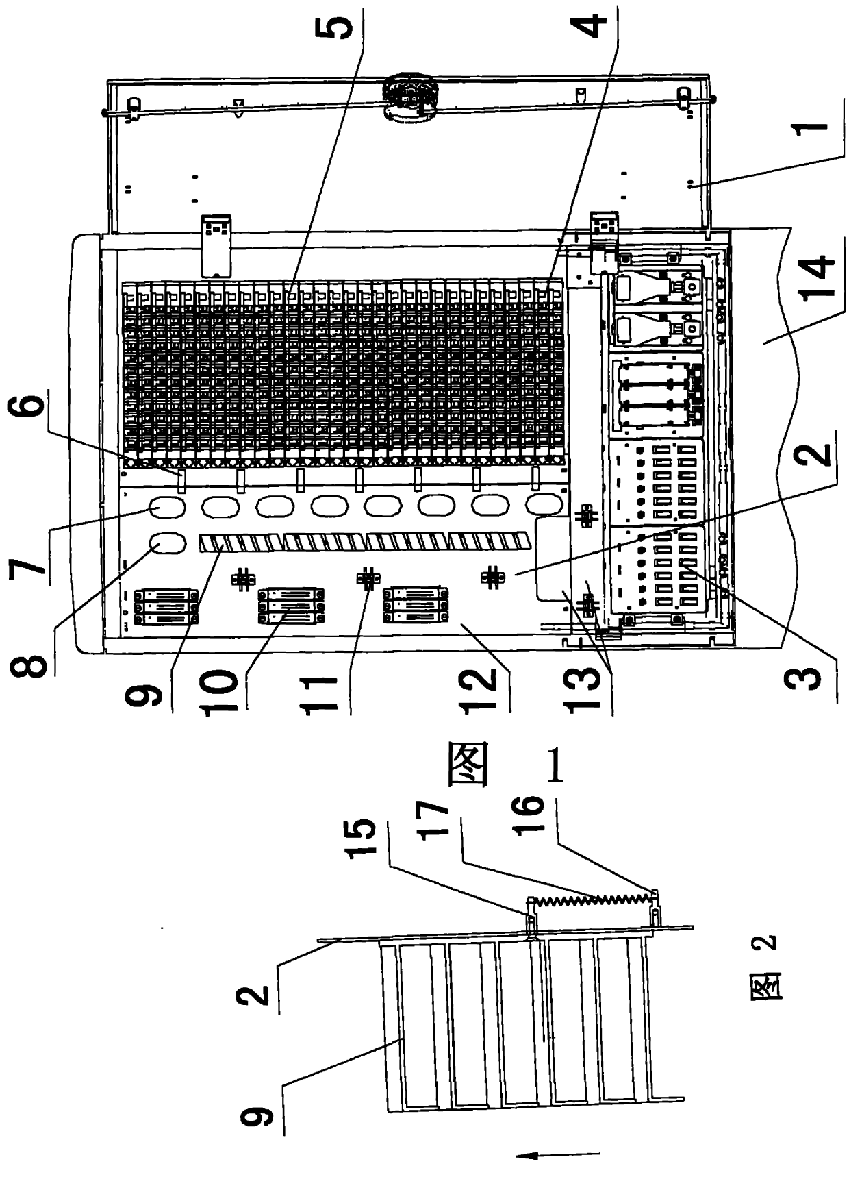
[0012] combined with figure 1 First, insert the two ends of the fiber jumper into the ports that need to be terminated, and lead them to the left at the same time. The fiber at the upper port goes up between the line hook group 6 and the fiber column group 7 through the transition disc fiber column 8 to the left line ring group. 11, the lower-end optical fiber goes up to the most suitable disk fiber column after the line hook group 6 and the disk fiber column group 7 turn, and goes down along the gap between the disk fiber column group 7 and the floating line ring group 9, and finally the redundant fiber is It will be accommodated in a suitable slot by the floating wire ring group 9, and a small amount of surplus fiber can be accommodated by adjusting the floating wire ring group 9. The termination of other optical jumpers can be completed simply by repeating the above steps.
Embodiment 2
[0013] Embodiment 2, FTTH optical cable transfer box access mode
[0014] combined with figure 1 , install and fix the optical splitter 10 in the leftmost channel, and put the input end along the left line to the lower crossbeam into the trunk port. Insert any ferrule (or a designated core) of the output end into any (or designated) distribution port, and lead the optical fiber to the left along the distribution port to the wire hook group 6 and the disk fiber column group 7 and go up to the most Appropriate disc fiber column turns afterward, and goes down along the gap between the disc fiber column group 7 and the floating wire ring group 9. The optical fiber near the output end of the optical splitter 10 goes down through the ring group 11, and finally the redundant fiber will be accommodated in a suitable slot by the floating ring group 9, and the trace remaining fiber can be adjusted by adjusting the floating ring group 9 containment. The remaining output ports that hav...
Embodiment 3
[0015] Embodiment 3, the access mode of terminalless optical cable transfer box (the pigtail after being fused with the trunk is directly terminated at the distribution port)
[0016] combined with figure 1 , insert the output port of the trunk into the wiring port that needs to be terminated, and the optical fiber at the top is led to the left to the wire hook group 6 and the disk fiber column group 7 and goes up through the transition disk fiber column 8 to the left line ring group 11 Introduced inside, the lower end optical fiber goes up between the wire hook group 6 and the disk fiber column group 7 to the most suitable disk fiber column, then turns, and goes down along the gap between the disk fiber column group 7 and the floating line ring group 9, and finally the redundant fiber is It will be accommodated in a suitable slot by the floating wire ring group 9, and a small amount of surplus fiber can be accommodated by adjusting the floating wire ring group 9. The pigtail...
PUM
 Abstract
Description
Claims
Application Information