
Pebble bed high temperature pile ball flow pipeline locker

A high-temperature reactor and latch technology, which is applied in the field of reactor equipment and can solve the problems of fuel element jamming and the like

Active Publication Date: 2012-02-08
CHINERGY CO LTD
View PDF0 Cites 0 Cited by
  • Summary
  • Abstract
  • Description
  • Claims
  • Application Information

AI Technical Summary

Problems solved by technology

Due to the particularity of the structure of the transfer conversion equipment, fuel elements may be jammed in the equipment

Method used


Image

  • Pebble bed high temperature pile ball flow pipeline locker
  • Pebble bed high temperature pile ball flow pipeline locker

Examples


Embodiment Construction

[0017] The following examples are used to illustrate the present invention, but are not intended to limit the scope of the present invention.

[0018] The specific implementation manners of the present invention will be further described in detail below in conjunction with the accompanying drawings and embodiments. The following examples are used to illustrate the present invention, but are not intended to limit the scope of the present invention.

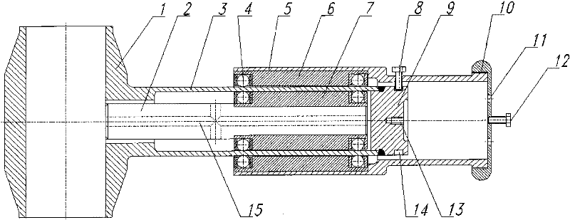
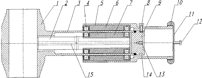
[0019] like figure 1 As shown, the pebble bed high temperature pile ball flow pipeline locker provided by the embodiment of the present invention is arranged on the outside of the ball passing pipe 1, and mainly includes: a lock shaft 2, a pressure bearing shell 3, a ball 4, a jacket 5, and an outer magnetic assembly 6. Inner magnetic group 7, positioning screw 8, head 9, end cover 10, air hole 11, locking screw 12, locking screw hole 13, positioning groove 14, diversion hole 15.

[0020] After connecting the ball joint 1 and the...


PUM


Abstract

The invention relates to a ball flow pipeline locker of a pebble bed high temperature reactor. The locker is arranged outside a ball run-through joint pipe and comprises a bearing shell, a locking shaft and a jacket, wherein one end of the bearing shell is connected with the ball run-through joint pipe, the internal space of the bearing shell is communicated with the ball run-through joint pipe, and the other end of the bearing shell is provided with a seal head; the locking shaft is arranged in the internal space of the bearing shell and an inner magnet assembly is arranged outside one end of the locking shaft; the jacket is sleeved outside the bearing shell; and an outer magnet assembly matched with the inner magnet assembly is arranged between the outer surface of the jacket and the inner surface of the bearing shell. The locker provides locking power and realizes isolation of atmosphere and pressure inside and outside equipment by means of synchronous movement of the inner and outer magnetic materials; the locker meets the requirement that the balls pass through the pipe smoothly without accident under normal ball flow circulation; and the locker effectively locks partial ball flow pipeline so as to safely and reliably prevent a fuel element from moving downwards continuously when downstream conveying and converting equipment is blocked by the balls.

Description

technical field [0001] The invention relates to a locker for a ball flow pipeline of a pebble bed high temperature reactor fuel loading and unloading system, which belongs to the field of reactor equipment. Background technique [0002] The fuel used in the high-temperature gas-cooled reactor nuclear power plant demonstration project (HTR-PM) is a spherical element with a diameter of 60 mm. The spherical fuel elements are loosely stacked in the core. , Multiple cycles of the core. During normal operation of the reactor, graphite balls flow from top to bottom in the reactor core and unloading pipe by gravity, and enter the fuel element after being sorted and singled out by the integrated unloading device at the lower end of the core unloading pipe Circulating ball flow pipeline. In the ball flow pipeline, the fuel elements also need to undergo a series of transportation conversion and burnup measurement. The elements that have not reached the target burnup depth will enter ...

Claims


Application Information

Patent Timeline
Patent Type & Authority Patents(China)
IPC IPC(8): G21C19/115
CPCY02E30/30
Inventor 李红克张海泉王鑫刘继国吴宗鑫张作义
Owner CHINERGY CO LTD
Learn More