Buck-boost composite DC/DC converter

A converter, buck-boost technology, applied in the field of DC/DC converters with buck-boost composite, can solve problems such as increased switching loss, increased output ripple, and system instability

Inactive Publication Date: 2010-07-14
BEIHANG UNIV
View PDF0 Cites 22 Cited by
  • Summary
  • Abstract
  • Description
  • Claims
  • Application Information

AI Technical Summary

Problems solved by technology

The advantage of the cascade method is that it maintains the characteristics of high conversion efficiency of a single Boost and Buck circuit (up to 96%), and at the same time overcomes the function of a single Boost and Buck that cannot be stepped up and down at the same time, ensuring that the output voltage and input voltage are always In the same direction, the stress of the switching element is low, but there is a coupling relationship between the front and rear stages, that is, the output of the previous stage is the input of the latter stage. When the output voltage target value is close to the input voltage, frequent switching between the front and rear stages will easily cause the system to oscillate , this kind of oscillation will not only increase the output ripple, reduce efficiency, and even cause system instability in severe cases; the latter two optimize the circuit topology, reduce the number of switch tubes, and solve the problem of Oscillation problems caused by it make the control more convenient, but the output voltage is reversed to the input voltage, the voltage and current stress of the switching element is much higher than the previous two, the switching loss increases, and the efficiency decreases. It is necessary to use a large capacity and high resistance high pressure components, resulting in higher costs

Method used


Image

  • Buck-boost composite DC/DC converter
  • Buck-boost composite DC/DC converter
  • Buck-boost composite DC/DC converter

Examples


Embodiment Construction

[0024] The present invention will be further described in detail below in conjunction with the accompanying drawings.

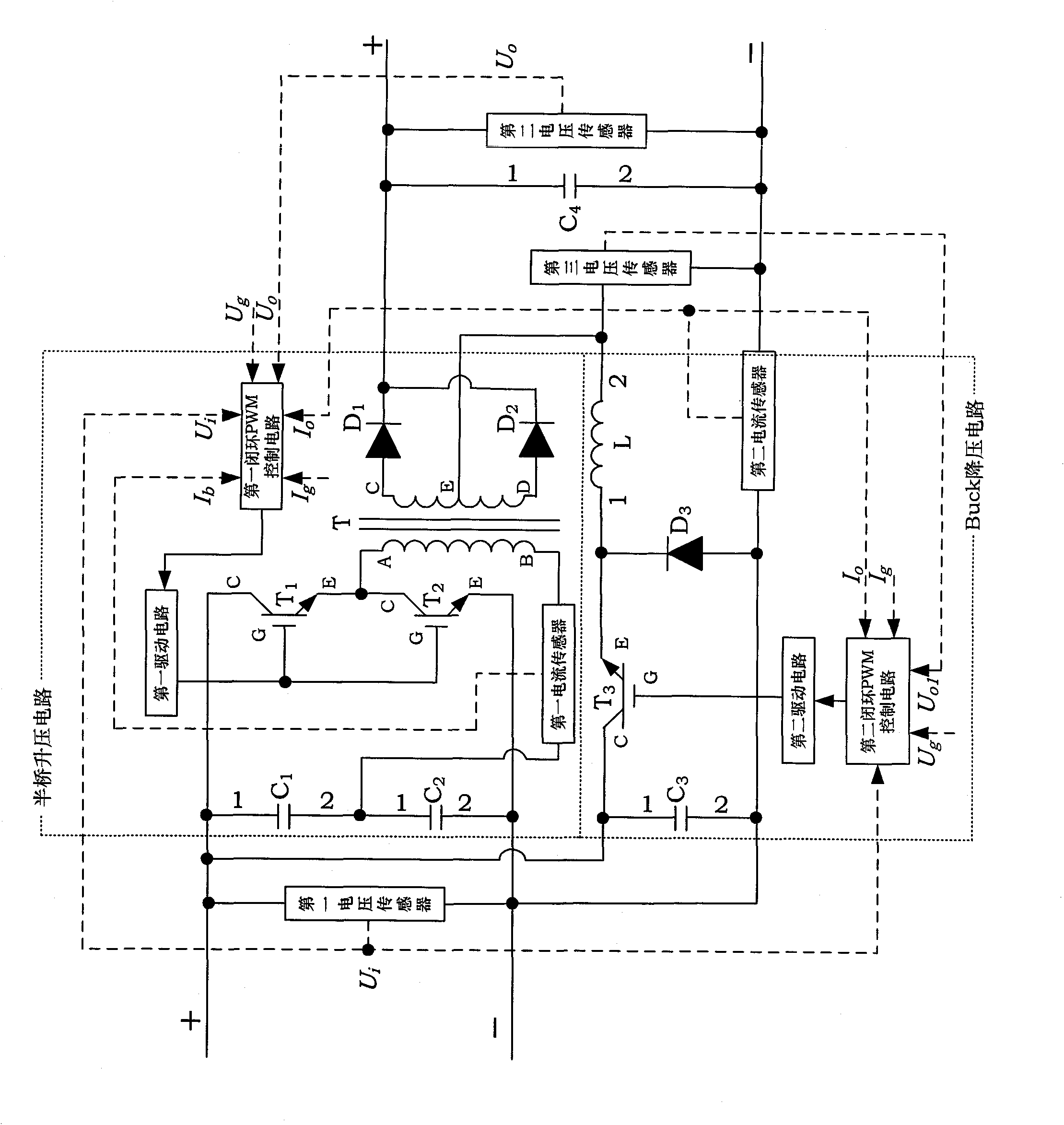
[0025] The present invention relates to a buck-boost composite DC / DC converter combined with a half-bridge and a Buck. The converter includes a Buck step-down circuit, a half-bridge booster circuit, a closed-loop PWM control circuit and a drive circuit.

[0026] In the present invention, the Buck step-down circuit is composed of the third filter capacitor C 3 , the third power switch tube T 3 , the third diode D 3 And filter inductance L composition.

[0027] In the present invention, the half-bridge boost circuit is composed of the first filter capacitor C 1 , the second filter capacitor C 2 , the first power switch tube T 1 , the second power switch tube T 2 , transformer T, first diode D 1 and the second diode D 2 composition.

[0028] In the present invention, the input stages of the Buck step-down circuit and the half-bridge booster circuit are ...


PUM


Abstract

The invention discloses a buck-boost composite DC / DC converter, which comprises a buck circuit, a half-bridge boost circuit, a closed-loop PWM control circuit and a driving circuit, wherein the input stages of the buck circuit and the half-bridge boost circuit are in a parallel connection mode, and the output stages are in a serial connection mode. When input ends are connected in parallel, the two circuits are mutually independent, no coupled relation exists, and the working mode depends on the magnitudes of the input voltage and the output voltage, so the problem of output oscillation of the converter is avoided. When output ends are connected in series, under the buck mode, the half-bridge boost circuit does not work, and the output voltage is approximately equal to the output voltage of the buck circuit; and under the boost mode, the buck circuit maintains a shoot-through state, and the output voltage is equal to the sum of the output voltage of the buck circuit and the output voltage of the half-bridge boost circuit. A half-bridge single circuit only provides the energy of an input and output voltage difference part, thereby increasing the efficiency of the whole converter.

Description

technical field [0001] The present invention relates to a DC / DC converter, more particularly, to a DC / DC converter with buck-boost compounding. Background technique [0002] With the economic development and social progress, the demand for energy is increasing day by day, and the major developed countries in the world have begun to pay attention to the research on the utilization of renewable energy. Photovoltaic cells have attracted more and more attention due to their advantages of no pollution, no noise, and inexhaustibility, and they will play an important role in future power supply systems. However, the output characteristics of photovoltaic cells are greatly affected by the external environment such as light intensity and temperature, and it is difficult to use the converted electric energy directly. Therefore, it is necessary to introduce a DC / DC converter to control its output characteristics to obtain the required output voltage. and current. Since the output vol...

Claims


Application Information

Patent Timeline
Patent Type & Authority Applications(China)
IPC IPC(8): H02M3/335
Inventor 齐铂金杜青徐国宁
Owner BEIHANG UNIV
Why Eureka
Try Eureka