Buck-boost device and buck-boost method applied to high-power pulse power supply system

A high-power pulse and power system technology, applied in output power conversion devices, control/regulation systems, high-efficiency power electronic conversion, etc., can solve the problems of complex circuit structure and high circuit production cost, and achieve low cost and good promotion value. Effect

Pending Publication Date: 2022-05-31
NAVAL UNIV OF ENG PLA
View PDF0 Cites 0 Cited by
  • Summary
  • Abstract
  • Description
  • Claims
  • Application Information

AI Technical Summary

Problems solved by technology

[0004] The present invention aims to solve the problem that the existing high-power pulse power supply system needs to use various voltage adjustment chips in order to realize the step-down and step-down of the input voltage, the circuit structure is very complicated, and the circuit production cost is relatively high.

Method used


Image

  • Buck-boost device and buck-boost method applied to high-power pulse power supply system
  • Buck-boost device and buck-boost method applied to high-power pulse power supply system
  • Buck-boost device and buck-boost method applied to high-power pulse power supply system

Examples


Embodiment Construction

[0030]The technical solutions in the embodiments of the present invention will be clearly and completely described below with reference to the accompanying drawings in the embodiments of the present invention. Obviously, the described embodiments are only a part of the embodiments of the present invention, but not all of the embodiments. Based on the embodiments of the present invention, all other embodiments obtained by those of ordinary skill in the art without creative efforts shall fall within the protection scope of the present invention.

[0031] It should be noted that all directional indications (such as up, down, left, right, front, back) in the embodiments of the present invention are only used to explain the relative positions of the various components in a certain posture (as shown in the accompanying drawings). relationship, movement situation, etc., if the specific posture changes, the directional indication changes accordingly.

[0032] In addition, the descript...


PUM


Abstract

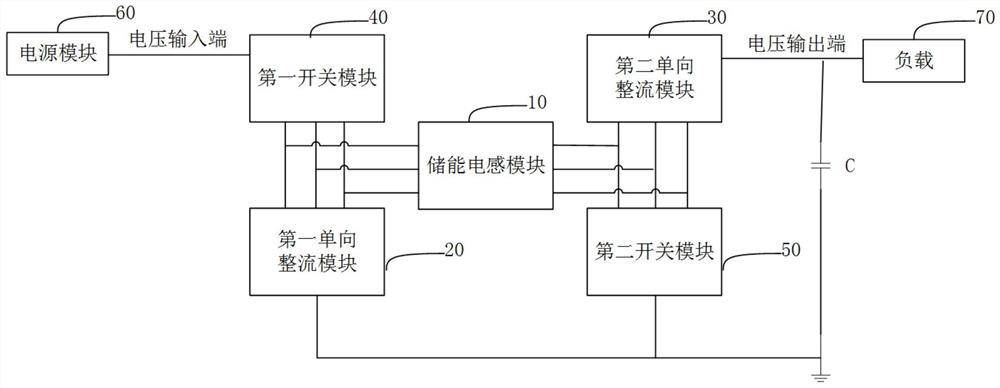
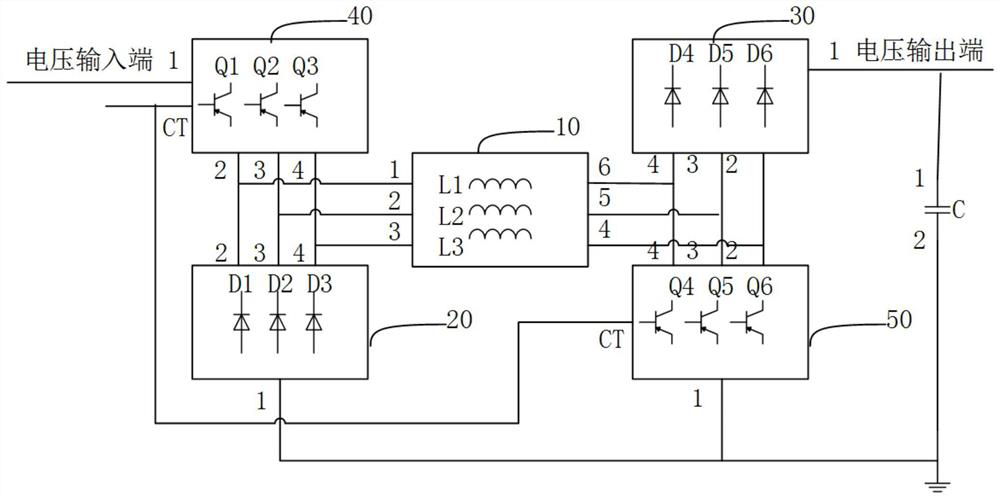
The invention discloses a buck-boost device applied to a high-power pulse power supply system. The buck-boost device comprises an energy storage inductor module, an energy storage capacitor, a first one-way rectifier module, a second one-way rectifier module, a first switch module and a second switch module, a first end of the first switch module is connected with a voltage input end, and a second end, a third end and a fourth end are connected with the energy storage inductor module and the first one-way rectifier module; the voltage output end is grounded through the energy storage capacitor; the first end of the second one-way rectifier module is connected with the voltage output end, and the second end, the third end and the fourth end are connected with the energy storage inductor module and the second switch module; the first switch module and the second switch module are used for being switched on or switched off according to a signal of a control end; the invention further discloses a corresponding buck-boost method, the cost of the circuit is low, boost or buck of the input voltage can be achieved, and the circuit has good popularization value.

Description

technical field [0001] This patent relates to the technical field of power electronics, in particular to a buck-boost device and a buck-boost method applied to a high-power pulse power supply system. Background technique [0002] In the high-power pulse power system, the input voltage range of the buck-boost device is 960V to 1402V, and the output voltage is required to rise to 1800V in a short time, and then stabilize at about 800V, during which the current remains stable. Therefore, when the input voltage is higher than the output voltage, the input voltage needs to be stepped down; and when the input voltage is lower than the output voltage, the input voltage needs to be boosted. In order to realize the normal power supply of the energy storage device to the system, a buck-boost circuit is usually arranged between the energy storage device and the load, which can boost or step down the input voltage to obtain the output voltage required by the load. [0003] At present, ...

Claims


Application Information

Patent Timeline
Patent Type & Authority Applications(China)
IPC IPC(8): H02M3/335
CPCH02M3/33569Y02B70/10
Inventor 郑伟刘子薇曾溶涛贾光勇钱翰宁岳非弘郑方正鲁梦昆
Owner NAVAL UNIV OF ENG PLA
Why Eureka
Try Eureka