
Method for starting Ethernet equipment and Ethernet equipment

A technology of Ethernet and equipment, applied in the field of Ethernet, can solve problems such as redundant backup application error action, network service interruption, Ethernet port can not receive and send messages, etc., to improve availability and application reliability, prevent The effect of wrong switching

Inactive Publication Date: 2010-07-14
RUIJIE NETWORKS CO LTD
View PDF0 Cites 2 Cited by
  • Summary
  • Abstract
  • Description
  • Claims
  • Application Information

AI Technical Summary

Problems solved by technology

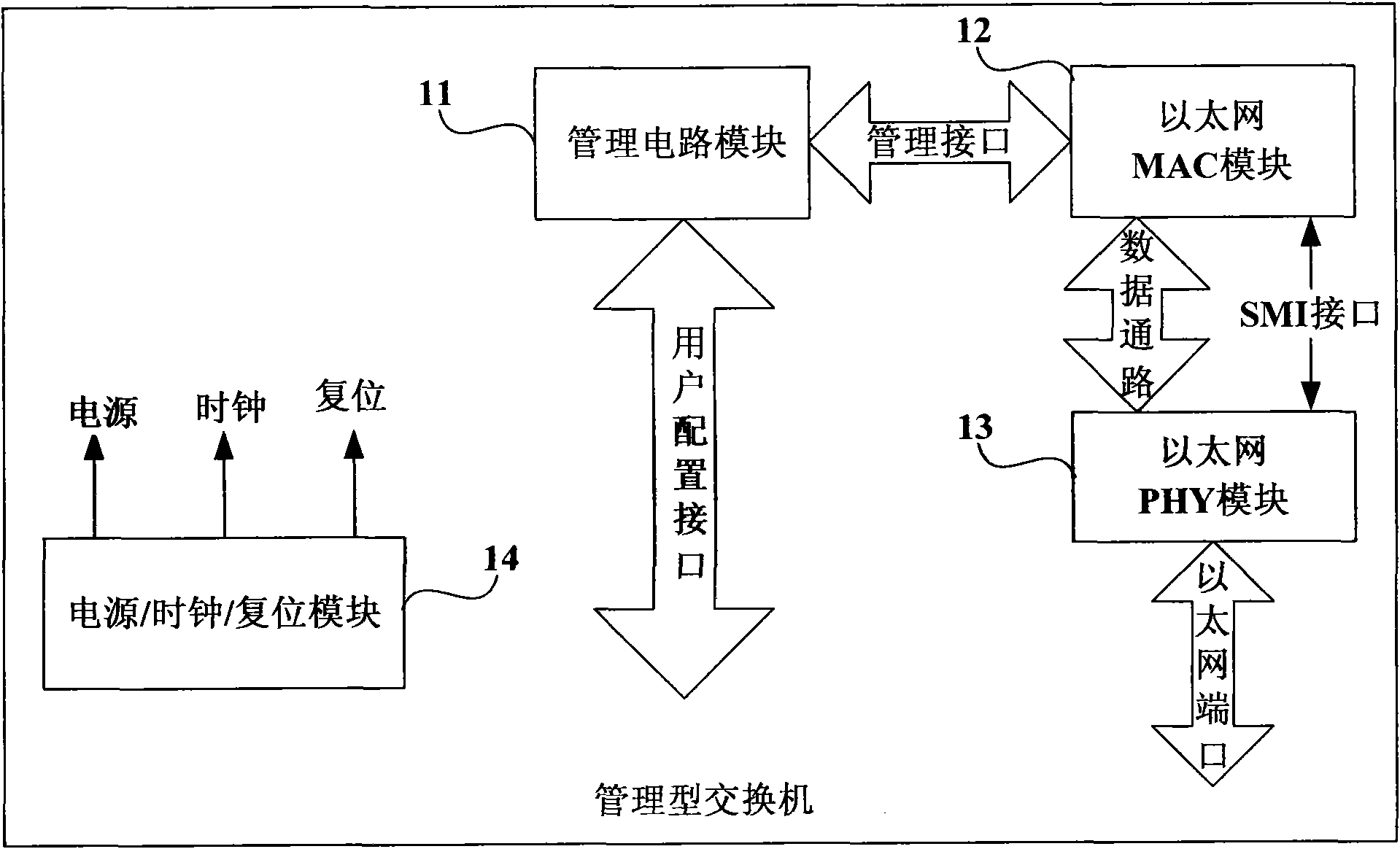
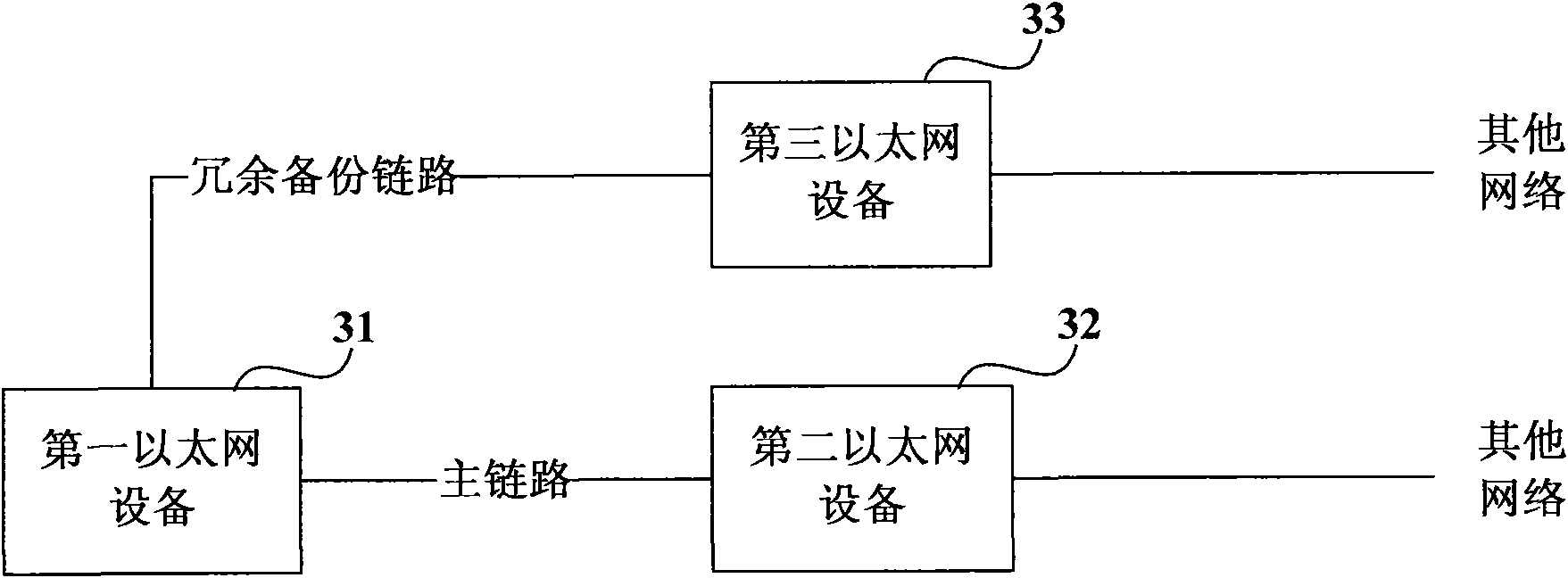
However, due to the needs of software startup and the initialization configuration of the Ethernet MAC module, there will be tens of seconds to several minutes after the connection is established and before the initialization configuration is completed, the second Ethernet device 32 cannot receive and send messages. Function
And, because the link between the first Ethernet device 31 and the second Ethernet device 32 is the main link, the priority is higher than the link between the first Ethernet device 31 and the third Ethernet device 33. An Ethernet device 31 immediately switches the network path back to the main link after detecting that the connection between the first Ethernet device 31 and the second Ethernet device 32 is established, resulting in interruption of network services
Similarly, other redundant backup protocols are inevitably affected by the fact that the ports that exist in the Ethernet device during the initial configuration stage cannot send and receive packets, and errors occur.
[0008] Therefore, there is an urgent need for a technical solution to solve the problem that the Ethernet port can only establish a connection but cannot receive and send packets within tens of seconds to a few minutes of the initialization stage after the Ethernet device is turned on, resulting in redundant backup applications. the problem of wrong action

Method used


Image

  • Method for starting Ethernet equipment and Ethernet equipment
  • Method for starting Ethernet equipment and Ethernet equipment
  • Method for starting Ethernet equipment and Ethernet equipment

Examples


Embodiment Construction

[0029] Figure 4 It is a flowchart of a method for starting an Ethernet device provided by an embodiment of the present invention. Such as Figure 4 As shown, the method includes:

[0030] Step 41, running the management circuit module;

[0031] For example, by performing operations such as power-on and reset, firstly let the management circuit module run, so as to control the startup of other modules.

[0032] Step 42, start the Ethernet MAC module under the control of the management circuit module, so that the Ethernet MAC module has message sending and receiving functions;

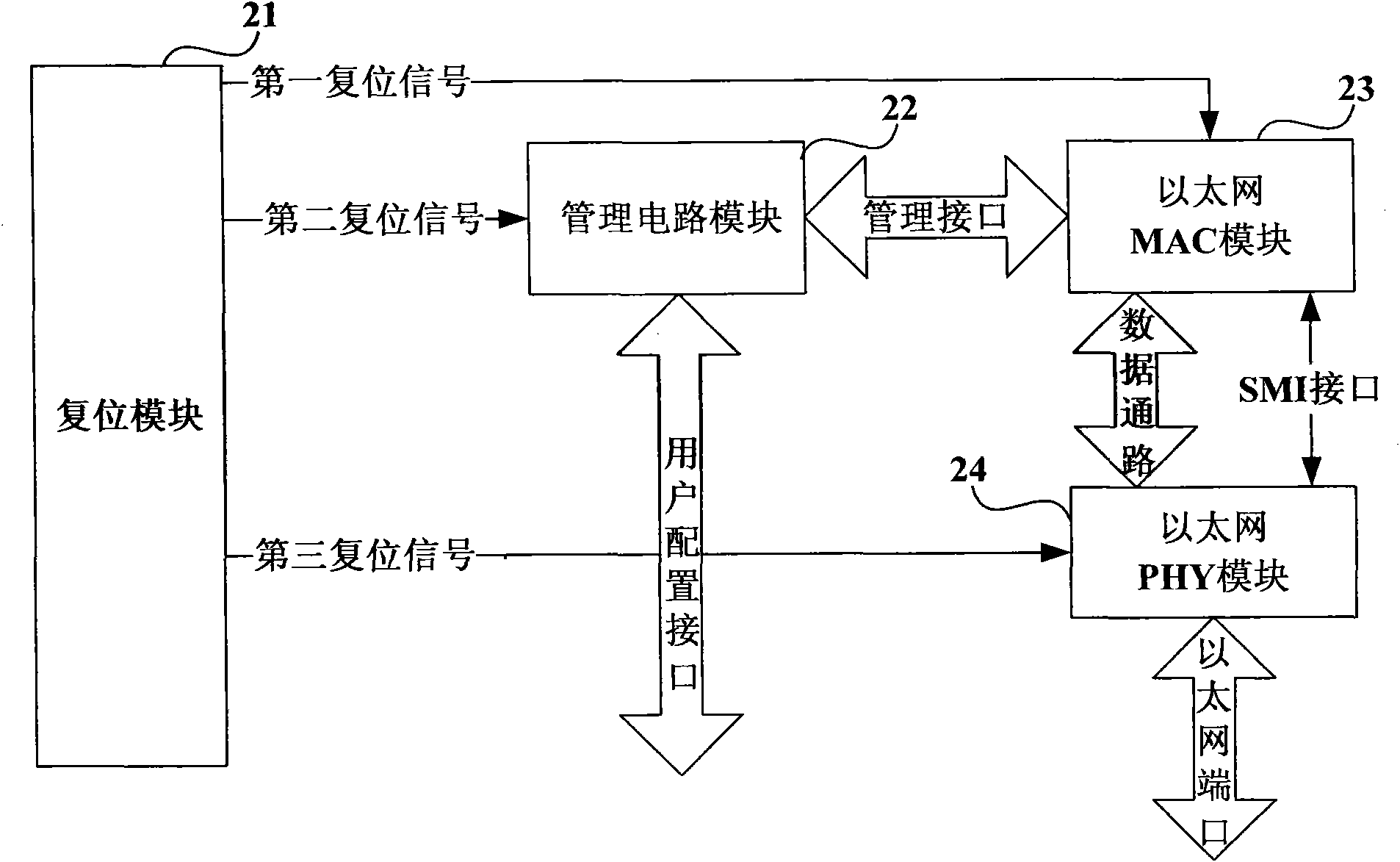
[0033] For example, the Ethernet MAC module is started by providing a reset signal to the Ethernet MAC module.

[0034] In a digital circuit system, as small as a chip or a functional module, the function of the reset signal is to restore its internal logic and state machine to the original state, that is to say, the module starts from the moment after the reset is completed. In progress. Such as ...


PUM


Abstract

The invention relates to a method for starting Ethernet equipment and the Ethernet equipment. The method comprises the following steps of: running a management circuit module; starting an Ethernet MAC module under the control of the management circuit module so that the Ethernet MAC module has the functions of sending and receiving messages; and starting an Ethernet PHY module under the control of the management circuit module after the Ethernet MAC module has the functions of sending and receiving the messages. In the technical scheme, by controlling the sequence of starting the Ethernet MAC module and the Ethernet PHY module in the Ethernet equipment, the Ethernet equipment and ports thereof have the characteristic of receiving and sending the messages after the Ethernet equipment and the ports thereof are connected; the error switching of all redundancy backup states in actual application is prevented; and the availability and the application reliability of the Ethernet equipment are improved.

Description

technical field [0001] The invention relates to the technical field of Ethernet, in particular to a method for starting an Ethernet device and the Ethernet device. Background technique [0002] Among LAN connection technologies, Ethernet is a standard established by the Institute of Electrical and Electronics Engineers (IEEE). The equipment used for Ethernet refers to the data communication equipment that provides one or more Ethernet ports. According to whether there is device management software inside the Ethernet device and the management circuit module necessary for the operation of the device management software, Ethernet devices are divided into two types: managed Ethernet devices and unmanaged Ethernet devices. Among them, managed Ethernet devices can rely on their internal device management software to provide users with various rich functions and practical applications, and have been more widely used in the field of data communication. [0003] Take the managed s...

Claims


Application Information

Patent Timeline
Patent Type & Authority Applications(China)
IPC IPC(8): H04L12/24H04L29/06H04L12/28
Inventor 韦锦驹
Owner RUIJIE NETWORKS CO LTD
Learn More