Sputtering apparatus and thin film formation method

A sputtering equipment and thin film technology, which is applied in the field of sputtering equipment and thin film formation, can solve different problems, achieve the effects of excellent uniformity, uniform gas distribution, and reduced substrate pollution

Active Publication Date: 2010-07-14
CANON ANELVA CORP
View PDF1 Cites 6 Cited by
  • Summary
  • Abstract
  • Description
  • Claims
  • Application Information

AI Technical Summary

Problems solved by technology

As a result, there may arise a problem that the quality of the film deposited on the substrate is different between the central portion and the peripheral portion

Method used


Image

  • Sputtering apparatus and thin film formation method
  • Sputtering apparatus and thin film formation method
  • Sputtering apparatus and thin film formation method

Examples


no. 1 approach

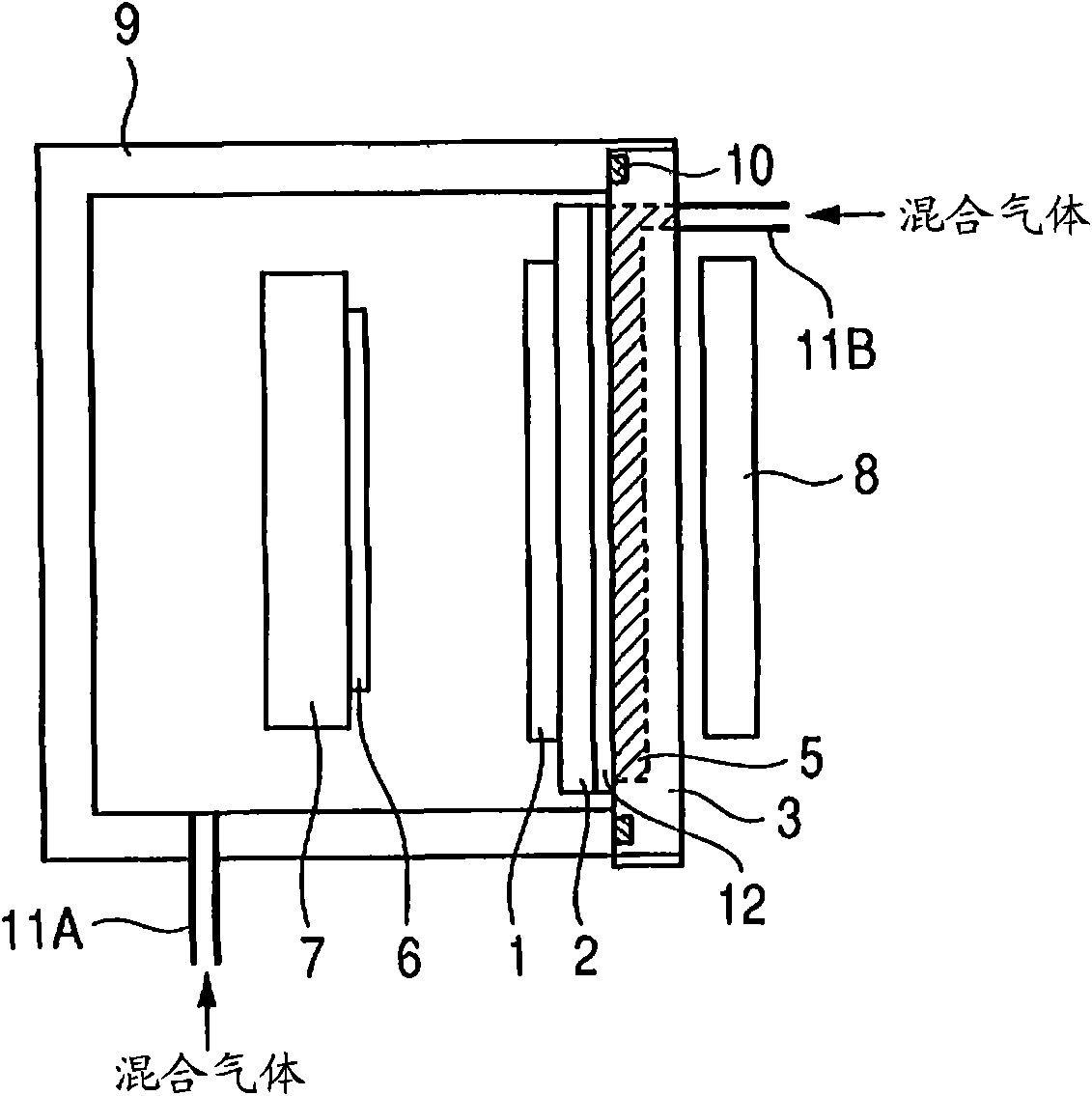
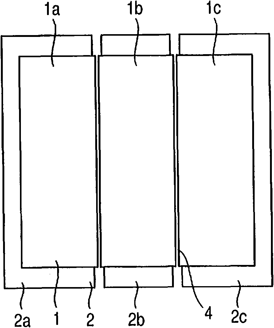
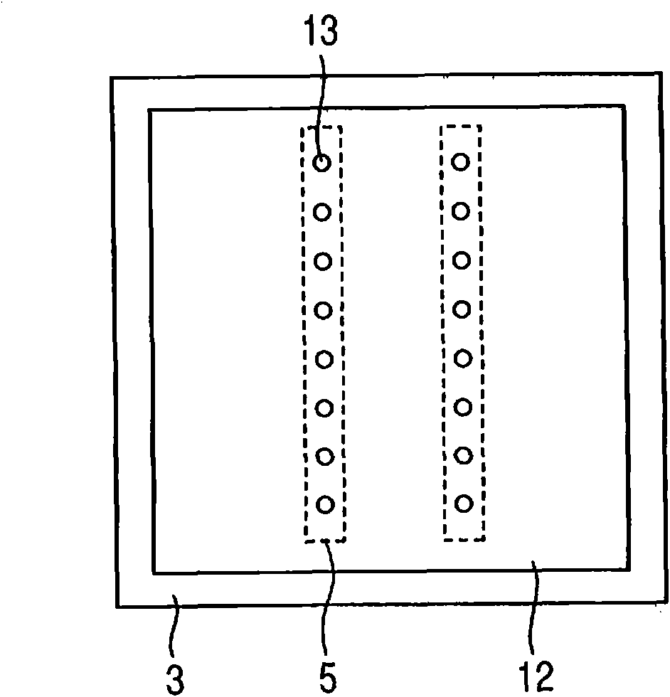
[0022] In the following, we will use Figure 1 to Figure 5 A sputtering device according to one embodiment of the present invention will be described.

[0023] figure 1 is a side sectional view showing a schematic configuration of a sputtering apparatus according to a first embodiment of the present invention. The sputtering apparatus includes a vacuum container 9 , a substrate holder 7 provided in the vacuum container 9 to support the substrate, and a cathode mechanism positioned opposite to the substrate. The cathode unit has a backing plate 2 for supporting the target 1 . The target 1 is supported on this backing plate 2 .

[0024] In addition, a first gas introduction mechanism for introducing gas from the gas supply pipe 11A to the vacuum container 9 and a second gas introduction mechanism for introducing gas from the gas introduction pipe 11B to the vacuum container 9 are provided in the sputtering apparatus. The first gas introduction mechanism is positioned apart f...

no. 2 approach

[0048] In the first embodiment, a form including both the first gas introduction mechanism and the second gas introduction mechanism has been described. In this embodiment, a form in which the first gas introduction mechanism is not provided will be described.

[0049] When the mixed gas containing the inert gas and the reactive gas is introduced from the second gas introducing means, both the inert gas and the reactive gas are introduced between the cathode means and the substrate 6 in the vacuum vessel 9 . In addition, the second gas introduction mechanism is designed to supply gas so as to reduce the concentration gradient of the reaction gas in the plasma-generating region between the cathode mechanism and the substrate 6 . Therefore, the inert gas and the reaction gas can be supplied to the region where plasma is generated without providing the first gas introduction mechanism including the gas introduction pipe 11A. In addition, the concentration gradient of the reactio...


PUM


Abstract

Provided are a sputtering apparatus and a thin film formation method by which uniform film qualities can be obtained even in a comparatively large substrate and occurrence of particles and nodules is suppressed. The sputtering apparatus has a vacuum container (9), a substrate holder (7) which holds a substrate (6), a cathode mechanism which is disposed at a position facing the substrate (6), and a second gas introduction mechanism which introduces gas into the vacuum container (9). The cathode mechanism has a plurality of targets (1a) to (1c) arranged with clearances therebetween and a plurality of backing plates (2a) to (2c) arranged with clearances therebetween. The clearances (14) between respective targets are smaller than clearances (15) between the respective backing plates. The clearances (14) overlap at least a part of the clearances (15). The second gas introduction mechanism introduces the gas through the clearances (15) and the clearances (14).

Description

technical field [0001] The present invention relates to a sputtering apparatus and a thin film forming method, and more particularly, to a sputtering apparatus and a thin film forming method which obtain a film excellent in uniformity quality and suppress generation of particles from a target. Background technique [0002] In reactive sputtering of a sputtering apparatus, a reactive gas such as oxygen or nitrogen is introduced together with an inert gas such as argon to cause sputtering in a vacuum chamber. In this reactive sputtering, as argon ions in the generated plasma collide with the target, particles of the target are knocked out. The particles of the target material react with the above-mentioned reaction gas, and a film formed of reactants produced by this reaction is deposited on the substrate. In addition, if the concentration of the reactive gas is high, the surface of the target reacts with the reactive gas to form a compound layer. As these species are sputte...

Claims


Application Information

Patent Timeline
Patent Type & Authority Applications(China)
IPC IPC(8): C23C14/34
CPCH01J37/3244C23C14/3407C23C14/0063C23C14/352H01J37/3435
Inventor 千叶俊伸吉冈胜也
Owner CANON ANELVA CORP
Why Eureka
Try Eureka