Gas distributor and system comprising gas distributor
A gas distributor and gas distribution technology, applied in chemical methods, chemical instruments and methods, and chemical/physical processes for reacting liquid and gas media, can solve problems such as low gas holdup in towers, dispersed bubble distribution, etc. , to achieve high gas holdup, large operating flexibility and easy control
- Summary
- Abstract
- Description
- Claims
- Application Information
AI Technical Summary
Problems solved by technology
Method used
Image
Examples
Embodiment 1
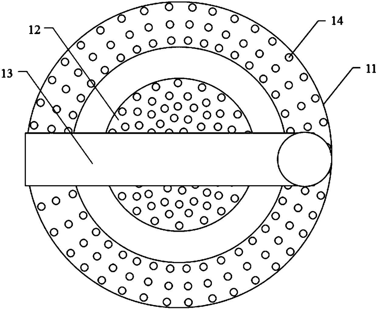
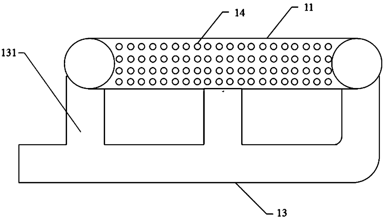
[0054] This embodiment provides a gas distributor (for a schematic diagram of its structure, refer to Figure 1a and Figure 1b ), the gas distributor includes an annular gas distribution pipe 11, a gas distribution box 12 located in the ring of the annular gas distribution pipe 11, and an inlet connected to the gas distribution pipe 11 and the gas distribution box 12 respectively. Trachea 13;
[0055] The air intake pipe 13 is respectively connected to the gas distribution pipe 11 and the gas distribution box 12 through the three air intake branches 131, so as to realize the fixing and air intake of the gas distribution pipe 11 and the gas distribution box 12;
[0056] Among the three air intake branches 131, one air intake branch 131 is connected to the gas distribution box 12, and the remaining two air intake branches 131 are connected to the radially opposite sides of the annular gas distribution pipe in pairs; the air intake pipe 13 Parallel to the plane where the annula...
Embodiment 2
[0060] Except for the following content, other content is identical with embodiment 1:
[0061] The air intake pipe 13 is respectively connected to the gas distribution pipe 11 and the gas distribution box 12 through the five air intake branches 131, so as to realize the fixing and air intake of the gas distribution pipe 11 and the gas distribution box 12;
[0062] Among the five air intake branches 131, one air intake branch 131 is connected to the gas distribution box 12, and the remaining four air intake branches 131 are connected to the radially opposite sides of the annular gas distribution pipe in pairs, and these four The connection ports between the two air intake branches 131 and the gas distribution pipe 11 are uniformly distributed on the gas distribution pipe; Air intake pipe 13 is vertical.
Embodiment 3
[0064] Except for the following content, other content is identical with embodiment 1:
[0065] On the gas distribution pipe 11, the air hole 14 close to the connection port of the gas distribution pipe 11 and the intake branch 131 has a small aperture, and is far away from the gas hole 14 at the connection port of the gas distribution pipe 11 and the intake branch 131. The aperture is large;
[0066] Preferably, on the gas distribution box 12, the air hole 14 close to the connection port of the gas distribution box 12 and the intake branch 131 has a small aperture, and is far away from the connection port of the gas distribution box 12 and the intake branch 131 The air holes 14 have a large aperture.
PUM
 Abstract
Description
Claims
Application Information
 - R&D
- Intellectual Property
- Life Sciences
- Materials
- Tech Scout
- Unparalleled Data Quality
- Higher Quality Content
- 60% Fewer Hallucinations
Browse by: Latest US Patents, China's latest patents, Technical Efficacy Thesaurus, Application Domain, Technology Topic, Popular Technical Reports.
© 2025 PatSnap. All rights reserved.Legal|Privacy policy|Modern Slavery Act Transparency Statement|Sitemap|About US| Contact US: help@patsnap.com


