
Ladle tilting mechanism

A technology of tipping mechanism and ladle, which is applied in the direction of casting molten material container, metal processing equipment, casting equipment, etc. It can solve the problems of difficult operation of the crane, long operation time of the crane, wear of the ladle trunnion, etc., and achieves a compact structure , Reduce the difficulty of operation and reduce the effect of taking time

Inactive Publication Date: 2010-07-21
DALIAN DESIGN INST CO LTD CHINA FIRST HEAVY IND +1
View PDF0 Cites 18 Cited by
  • Summary
  • Abstract
  • Description
  • Claims
  • Application Information

AI Technical Summary

Problems solved by technology

This method takes a long time to operate the crane, and the operation of the crane is difficult; the ladle trunnion itself is used as the lifting point and hinge point, which seriously wears the ladle trunnion and makes the ladle prematurely scrapped

Method used


Image

  • Ladle tilting mechanism
  • Ladle tilting mechanism
  • Ladle tilting mechanism

Examples


Embodiment Construction

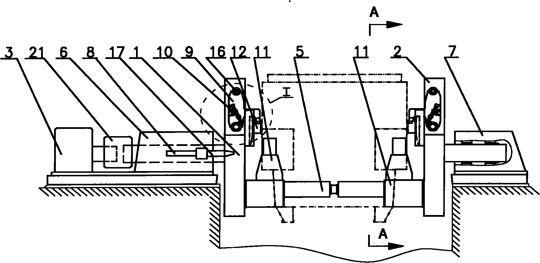
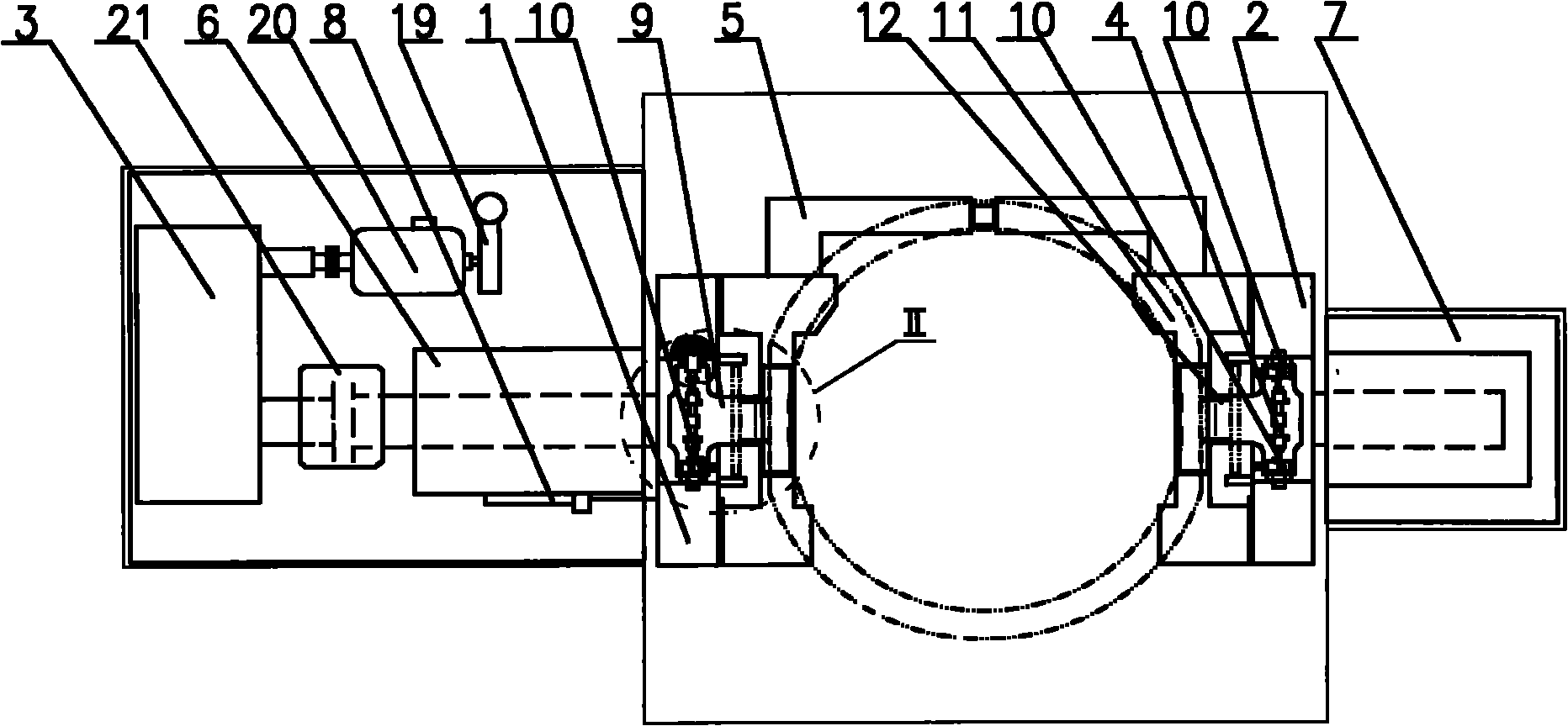
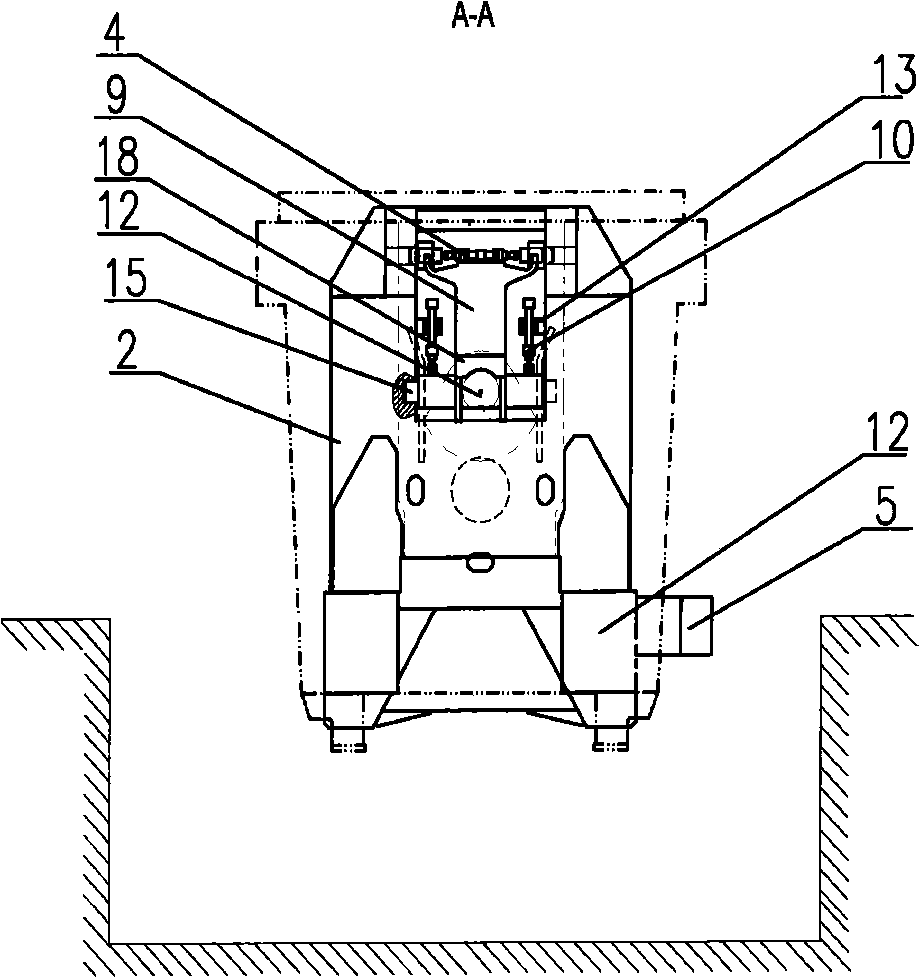
[0021] figure 1 , 2 , 3, 4, and 5 show specific embodiments of the present invention, which are a kind of ladle tipping mechanism installed in a large-scale steelmaking workshop; it is characterized in that: in the foundation pit, circular trunnions 12 supporting ladle both sides are symmetrically installed The U-shaped mount 11 is connected with the connecting beam 5 at the rear side between the two U-shaped mounts 11, wherein the U-shaped mount 11 on the left side is connected with the driving tipping frame 1, and the U-shaped mount 11 on the right is connected with the The moving tilting frame 2 is connected; the concentric rotating shaft is connected at the center of the outer surface of the driving tilting frame 1 and the driven tilting frame 2, and the rotating shaft of the driven tilting frame 2 is packed into the driven side rotary bracket 7 In the shaft hole, the rotating shaft of the driving tipping frame 1 is connected to the output shaft in the electric transmissi...


PUM


Abstract

The invention relates to a ladle tilting mechanism, which is characterized in that U-shaped brackets for supporting ladle round trunnions are arranged in a pit in a symmetric manner, a tie-beam is used for connecting two U-shaped brackets, one U-shaped bracket is connected with a drive tilting frame, and the other U-shaped bracket is connected with a driven tilting frame; a concentric rotation shaft is respectively arranged at the outer side of each of the tilting frame, the rotation shaft of the drive tilting frame is connected with an electric drive device via a drive side revolting bracket, and the rotation shaft of the driven tilting frame is arranged in a driven side revolting bracket; the two tilting frames are respectively provided with a clamping frame mechanism for clamping the round trunnions; each clamping frame mechanism is provided with a locking mechanism; and the outer side of the drive side revolting bracket is provided with a locating mechanism for locating the ladle rotation angle. The invention has the advantages of reasonable design, compact structure, safe operation, convenient use and the like; and ladles can rotate within 0-18 degrees without being hoisted by a crown block to tilt, thus reducing occupied time and operation difficulty of the crown block, lowering abrasion of the ladle trunnions, prolonging the service life thereof.

Description

technical field [0001] The invention belongs to steelmaking auxiliary mechanical equipment, in particular to a ladle tipping mechanism. Background technique [0002] At present, the method of maintaining and replacing the sliding nozzle equipment of the "round trunnion type steel ladle" in China is: place the steel ladle on the ground, lift the steel ladle with the big hook of the crane, lift the auxiliary lifting lug with the small hook, and the steel ladle Rotate 90 degrees and land on the support on the ground. After maintenance of the ladle sliding nozzle, use the large and small hooks of the crown block to cooperate, rotate the ladle to 180 degrees, dump the remaining molten steel and steel slag, and then use the large and small hooks of the crown block to cooperate to return to the ground. 0 degree state. This method takes a long time to operate the crane, and the operation of the crane is difficult; the ladle trunnion itself is used as the lifting point and hinge poi...

Claims


Application Information

Patent Timeline
Patent Type & Authority Applications(China)
IPC IPC(8): B22D41/06
Inventor 邢思深李伟
Owner DALIAN DESIGN INST CO LTD CHINA FIRST HEAVY IND
Learn More