Universal joint

A technology of universal joints and ball joints, applied in the field of universal joints, which can solve problems such as poor clamping effect, easy shaking during use, and poor anti-torsion strength

Active Publication Date: 2010-07-21
胡厚飞
View PDF1 Cites 9 Cited by
  • Summary
  • Abstract
  • Description
  • Claims
  • Application Information

AI Technical Summary

Problems solved by technology

[0008] The purpose of the present invention is to overcome the disadvantages of poor clamping effect of traditional adapters, poor anti-torsion strength, and easy shaking during use

Method used


Image

  • Universal joint
  • Universal joint
  • Universal joint

Examples


Embodiment Construction

[0030] Regarding the technology, means and effects used in the present invention, a preferred embodiment is given and described in detail below with drawings, which are for illustration purposes only, and are not limited by this structure in the patent application.

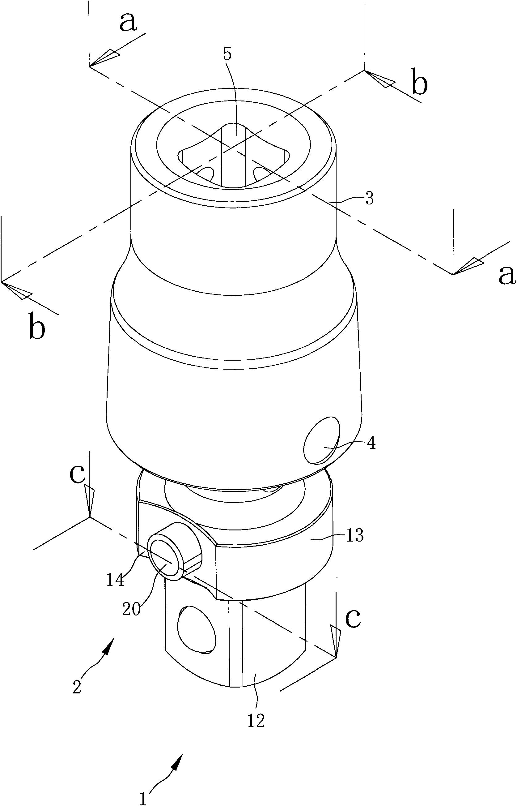
[0031] refer to figure 1 , is a three-dimensional appearance view of the universal joint of the present invention. The universal joint of the present invention includes a body 1, a control device 2 and a linkage 3;

[0032] One end of the link 3 is provided with a drive hole 5 for connecting a power tool, such as an air tool or an electric tool, so that the link 3 can be driven by the power tool to rotate.

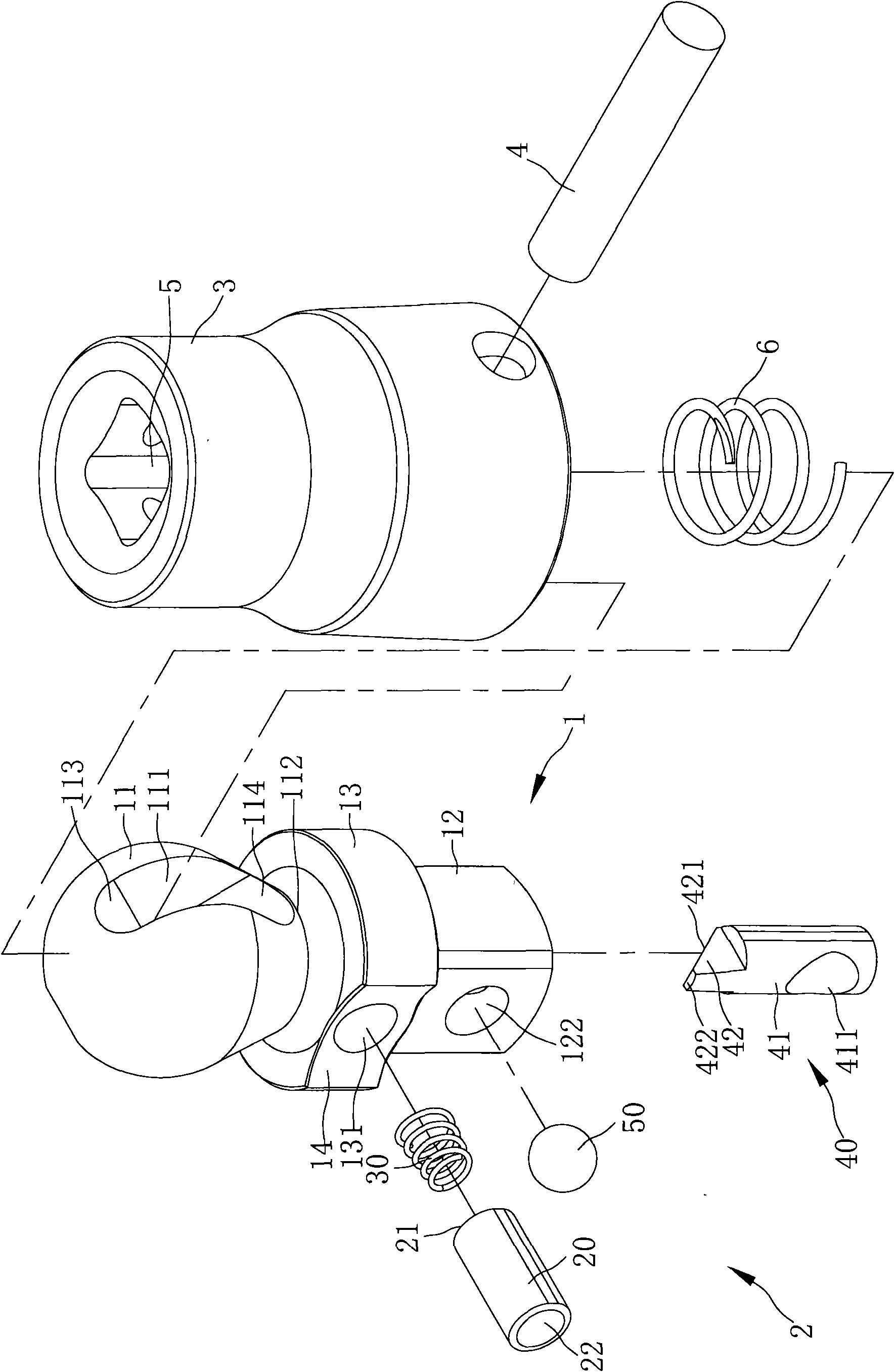
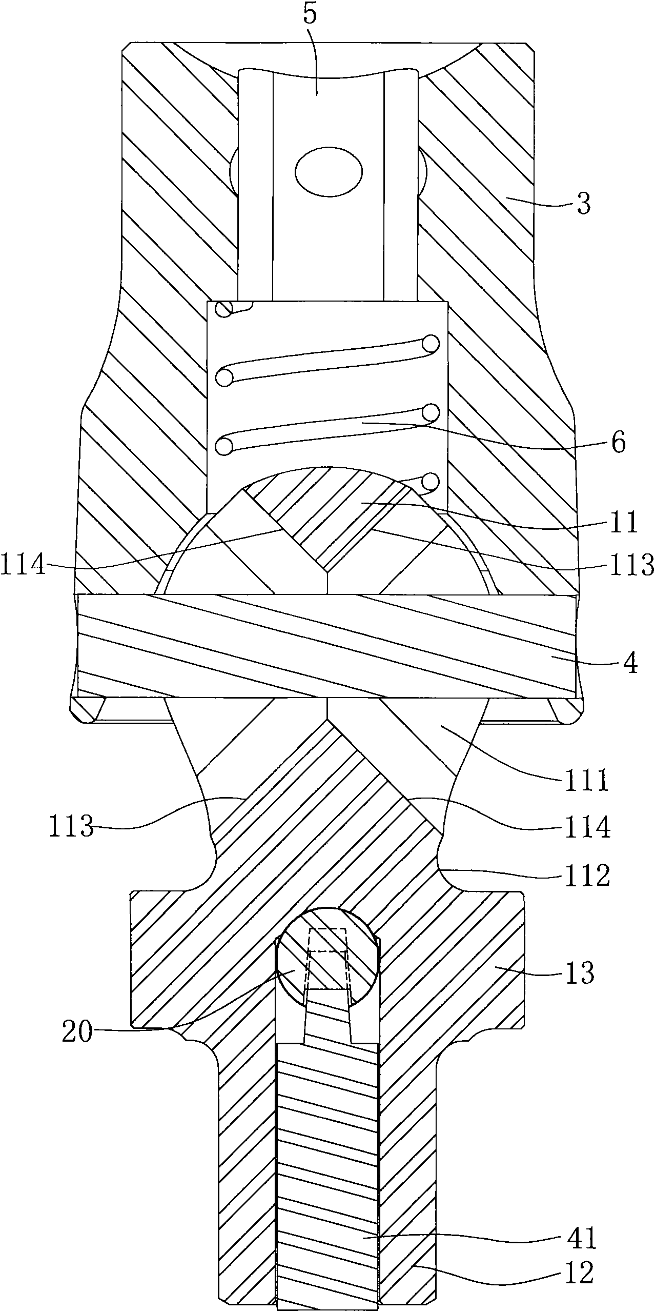
[0033] refer to Figure 2 to Figure 4 , the body 1 has a ball head 11 and a drive head 12, the ball head 11 is provided with a through hole 111 with an elliptical cross section (such as Figure 4 ), the through hole 111 can be pivotally connected to the linkage 3 through a pin 4, forming a complete universa...


PUM


Abstract

The invention discloses a universal joint, which comprises a linkage piece, a body and a control device. The linkage piece is provided with a driving hole which is connected with a power rotation tool. The body is provided with a ball head and a driving head, wherein the ball head is pivoted to the linkage piece through a pin so as to achieve the effect of multi-angle rotation, and the driving head can bear an object to be driven. A reinforced part is annularly arranged between the ball head and the driving head. A groove is formed on one side of the reinforced part, and a control hole is formed in the groove. The control device comprises a control piece, wherein the control piece is provided with a propping end arranged in the control hole and a control end hidden in the groove. Therefore, the control end of the control piece does not impact the hands during rotation of the universal joint, and the control piece is not damaged due to the collision of hard objects during the rotation.

Description

technical field [0001] The present invention mainly discloses a universal joint, especially a control device with a locking sleeve on the universal joint, and when the universal joint is driven to rotate by a power rotating tool, the hand on the universal joint will not be affected by the control device. Injury due to collision, and no damage to control parts caused by collision with hard objects during rotation. Background technique [0002] A traditional powered rotary tool, such as an air tool or an electric tool, engages a socket and then tightens or loosens locks in the engine compartment of the car. In addition to the sleeve, there is also a long connecting rod in the shape of a square head. This long connecting rod can be connected between the power rotating tool and the sleeve. Many, many locking parts are inaccessible to the power rotary tool itself, and a long post must be used to solve this problem. [0003] In addition to the above-mentioned situation, there is...

Claims


Application Information

Patent Timeline
Patent Type & Authority Applications(China)
IPC IPC(8): F16D3/202B25B23/00
Inventor 胡厚飞
Owner 胡厚飞
Why Eureka
Try Eureka