Permanent-magnet speed governor

A permanent magnet governor and permanent magnet technology, applied in the direction of asynchronous induction clutch/brake, etc., can solve problems such as electromagnetic interference, many fault points, and insufficient stability, and achieve the effect of reducing vibration

Inactive Publication Date: 2010-07-21
王荣松
View PDF4 Cites 6 Cited by
  • Summary
  • Abstract
  • Description
  • Claims
  • Application Information

AI Technical Summary

Problems solved by technology

Although the hydraulic coupling can adjust the speed and save energy to a certain extent, its efficiency is low and it is not stable enough
Inverter and internal feedback chopper speed regulation use the method of directly changing the motor speed to adjust the system and load, which has high efficiency and good energy-saving effect, but because there are many electrical components and many fault points, it has high environmental requirements and life cycle Short and has electromagnetic interference

Method used


Image

  • Permanent-magnet speed governor
  • Permanent-magnet speed governor
  • Permanent-magnet speed governor

Examples


Embodiment Construction

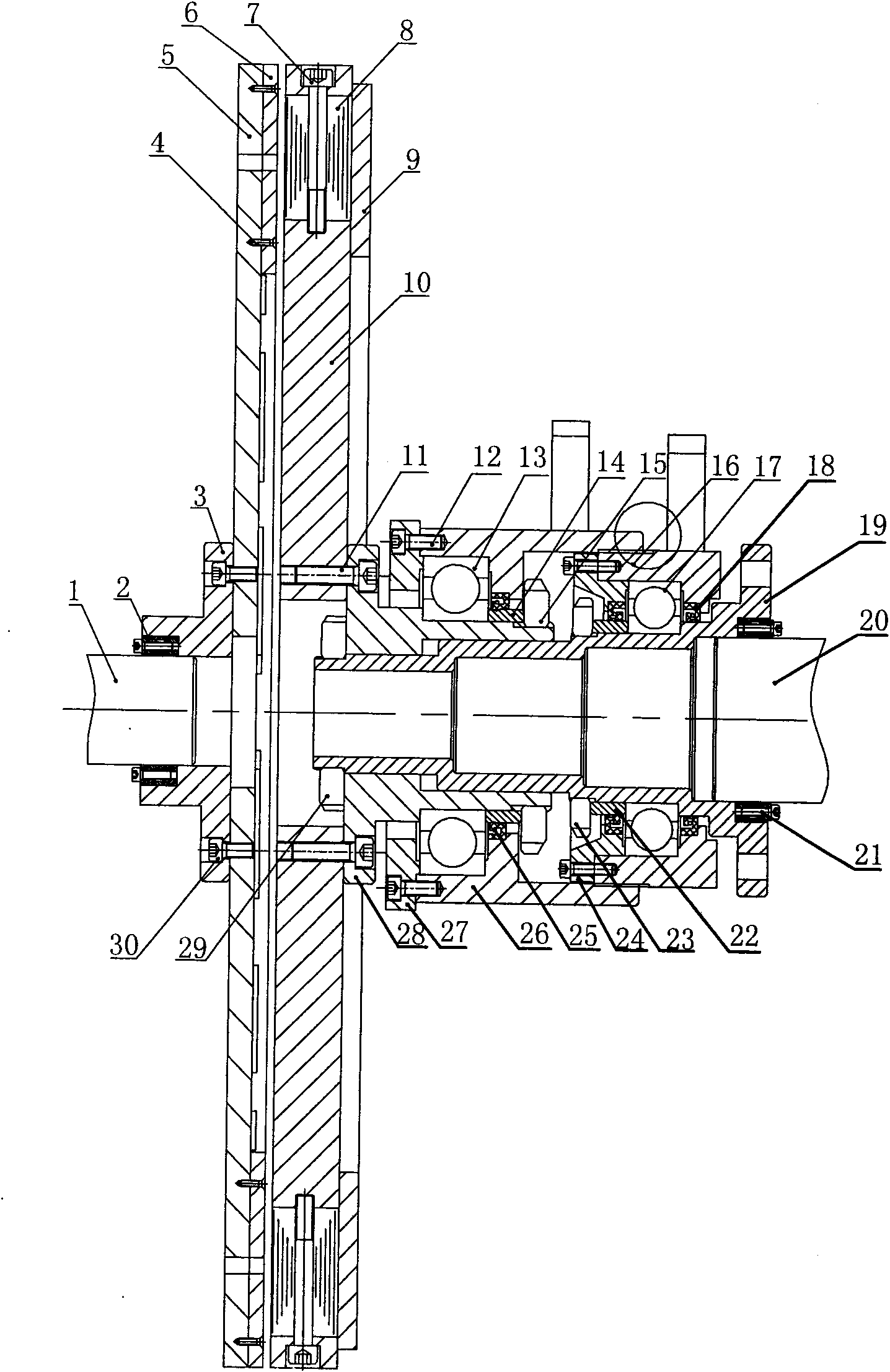
[0026] Referring now to the accompanying drawings in the description, the permanent magnet governor of the present invention will be further described in conjunction with specific embodiments.

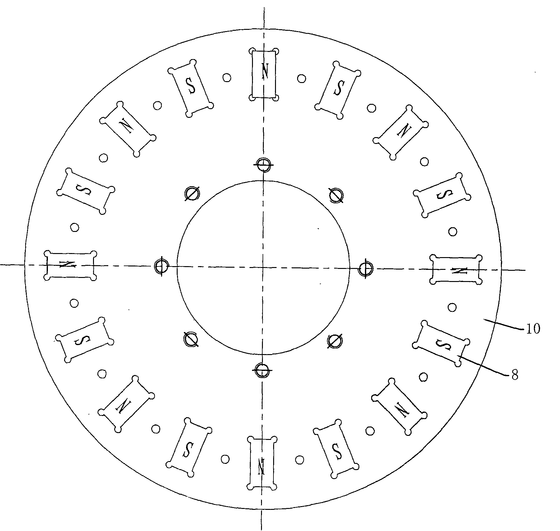
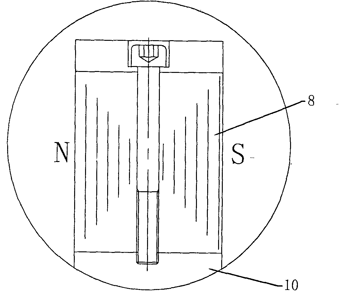
[0027] Working principle: The N and S poles of the magnets on the permanent disk are arranged adjacent to each other, and the magnetic field lines pass through the corresponding conductor disks. When the two move relative to each other, the conductor disks cut the magnetic force lines, and eddy currents are generated in the conductor disks. The current in turn generates an anti-magnetic field, which prevents the relative motion between the two, thereby realizing the torque transmission between the two. The greater the strength of the magnetic field passing between the two, the greater the transmitted torque; the faster the relative movement, the greater the transmitted torque; the greater the speed difference, the greater the repulsive force between the two. When other factors are fixe...


PUM


Abstract

The invention relates to a permanent-magnet speed governor, which comprises a first shaft and a second shaft, wherein the first shaft and the second shaft are coaxial, a conductor disc is installed on the first shaft and the second shaft is connected with a permanent-magnet rotating disc. The conductor disc and the permanent-magnet are placed close to each other. The conductor disc is formed by an outer rotating disc made of ferromagnetic material and an inner rotating disc made of conductor material, wherein the outer rotating disc and the inner rotating disc are attached together. The permanent-magnet rotating disc is made of non-ferromagnetic material. A group of permanent magnets are annularly installed on the permanent-magnet rotating disc. The magnetic pole direction of the permanent magnets is in parallel with the axis of the rotating disc, and every two adjacent ends are heteropolar. The invention has the advantages that non-contact power transmission is realized, the vibration is reduced, the motor can be started up fully with no load during startup, the torque transferred between the permanent-magnet rotating disc and the conductor disc can be varied through adjusting a handle installed on an outer sleeve to push a bearing to axially move on the shaft, to push-and-pull the permanent-magnet rotating disc to axially move and to vary the air gap between the permanent-magnet rotating disc and the conductor disc, repeatable, adjustable and controllable output torque and rotating speed can be realized, and the goal of speed regulation and energy saving is obtained.

Description

technical field [0001] The invention relates to a motor-driven speed regulating device, in particular to a permanent magnet speed regulating device adopting the principle of permanent magnet eddy current induction. Background technique [0002] Existing motor systems, especially centrifugal equipment systems, mainly use the following methods to regulate flow and pressure: damper baffles, valves, hydraulic couplings, frequency converters, and internal feedback chopper speed regulation. Dampers and valves are traditional methods, which can effectively adjust the flow or pressure, but the disadvantages are also obvious: they are not energy-saving, and they are easy to cause shocks in the system. Although the hydraulic coupling can adjust the speed and save energy to a certain extent, its efficiency is low and it is not stable enough. Inverter and internal feedback chopper speed regulation use the method of directly changing the motor speed to adjust the system and load, which ...

Claims


Application Information

Patent Timeline
Patent Type & Authority Applications(China)
IPC IPC(8): H02K49/04
Inventor 王荣松
Owner 王荣松
Why Eureka
Try Eureka